
A water-cooled head buckle structure

A water-cooled head and buckle technology, applied to instruments, electrical digital data processing, electrical components, etc., can solve problems such as high R&D costs, inability to uniformly control risks, and inability to achieve mass production, and achieve the effect of saving R&D costs

Pending Publication Date: 2019-01-18
ASIA VITAL COMPONENTS (CHINA) CO LTD
View PDF0 Cites 3 Cited by
  • Summary
  • Abstract
  • Description
  • Claims
  • Application Information

AI Technical Summary

Problems solved by technology

[0004] The positions of the plurality of locking holes of the upper cover of the existing water-cooled plate and the plurality of locking holes of the lower cover are designed according to the specifications and models of the heating elements of the main board and the requirements of the manufacturer. , because heating elements of different specifications and models (such as central processing unit, graphics card chip (GPU), north-south bridge chip or ASIC chip) require water-cooling plates with different locking hole positions, such as CPUs of different specifications and models of the same brand (such as INTEL I3-CPU or INTEL I7-CPU) it is necessary to design a water-cooled plate with different locking hole positions (for example, the water-cooled plate corresponding to INTEL I3-CPU is designed with 4 locking holes in the four corners of the water-cooled plate or Corresponding design of water-cooling board for Intelli5-CPU (6 locking holes are set on the upper and lower sides of the water-cooling board), or CPUs of different brands (such as INTEL I7-CPU or AMD Ryzen7-CPU) also need corresponding design Another water-cooling board with different locking hole positions (for example, the water-cooling board corresponding to INTEL I7-CPU design 5 locking holes at the corner of the water-cooling board or the water-cooling board corresponding to AMD Ryzen7-CPU design 8 locking holes It is installed on the left and right sides of the water-cooled plate), so that the versatility of the water-cooled plate is poor, so that the production factory needs to design the mold corresponding to the main board and heating element for each water-cooled plate, resulting in separate production, design and development costs High and high production costs, and many problems such as mass production, inability to unify and high risk of control
[0005] In addition, both the top cover and the bottom plate of the existing water-cooled plate are manufactured separately by computer numerical control (CNC) processing, and the top cover and the bottom plate are connected together by brazing, but the top cover is Both the upper cover and the bottom plate are made of the same copper material, and additional locking holes for locking with the main board must be reserved on the two, so that the upper cover and the bottom plate need to be extended outward for more in manufacturing. Locking holes are set out of the position, resulting in a large overall water-cooled plate and heavy weight, which in turn increases the cost

Method used


Image

  • A water-cooled head buckle structure
  • A water-cooled head buckle structure
  • A water-cooled head buckle structure

Examples


Embodiment Construction

[0041] The above-mentioned purpose of the present invention and its structural and functional characteristics will be described according to the preferred embodiments of the accompanying drawings.

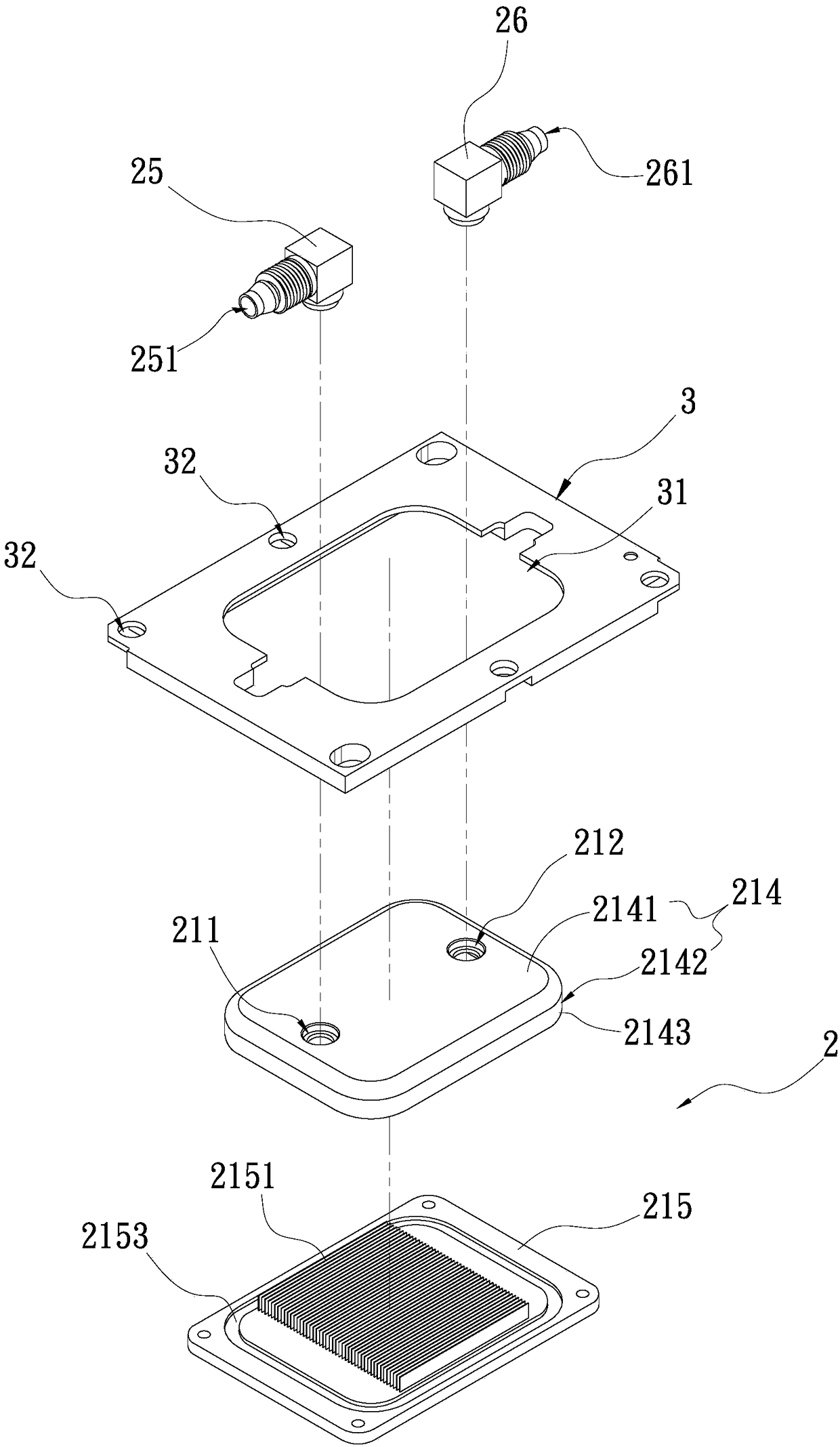
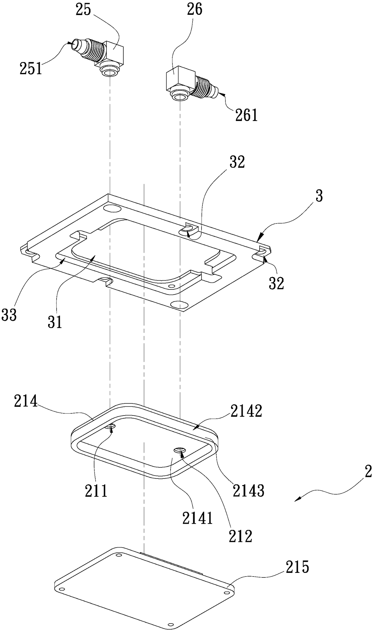
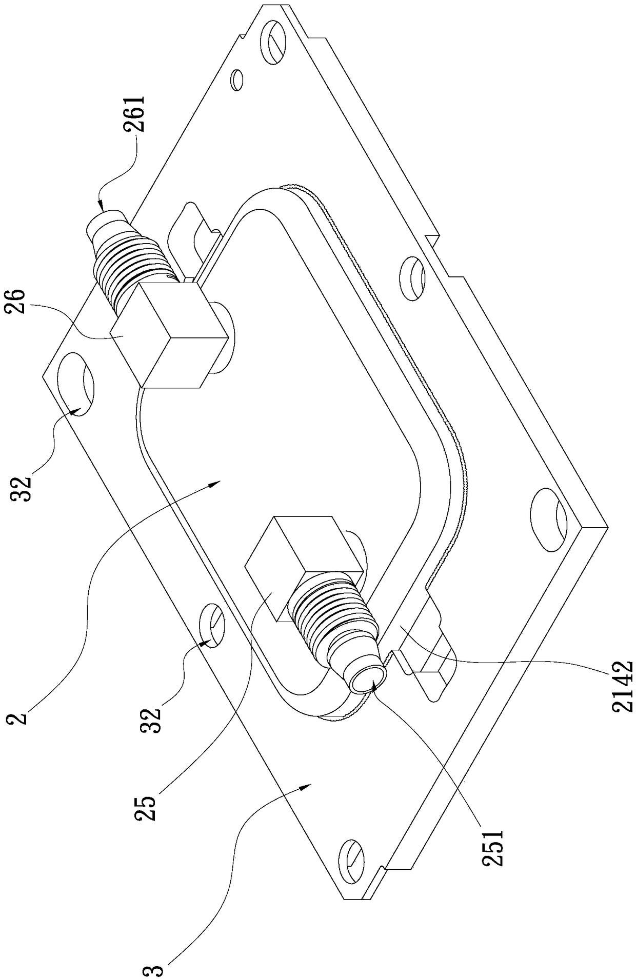
[0042] The present invention is a water-cooled head buckle structure, please refer to Figure 1A It is a three-dimensional exploded schematic view of the first embodiment of the present invention; Figure 1B It is a perspective exploded schematic diagram of another viewing angle of the first embodiment of the present invention; Figure 2A It is a three-dimensional combination schematic diagram of the first embodiment of the present invention; Figure 2B It is a three-dimensional combined partial cross-sectional schematic diagram of the first embodiment of the present invention; Figure 3A It is an exploded schematic diagram of the implementation form of the first embodiment of the present invention; Figure 3B It is a combined schematic diagram of the implementation style of the ...


PUM


Abstract

A water-cooled head buckle structure which is arranged on a water-cooled head., and is connected with a motherboard provided with a heating element and attached to the water-cooling head, The water-cooled head fastener structure comprises a fastener, wherein the fastener has a hollow opening and a plurality of through holes arranged along a circumferential side of the fastener, the plurality of through holes are used for fixing a plurality of fasteners on the main board, and the opening of the fastener is sleeved on the water-cooled head, so that the water-cooled head receives the fastener; The fastener of the invention can adjust the position of the through hole of the heating element according to the manufacturer's brand and the specification type design of the heating element on the main board.

Description

technical field [0001] The invention relates to a buckle structure for a water-cooled head, in particular to a buckle structure for a water-cooled head that reduces costs and improves production efficiency. Background technique [0002] With the advancement of science and technology, the operating frequency of electronic products (such as computers, servers or communication chassis) is getting faster and faster, so that the heat generated during operation is also increasing, and the relative heat dissipation requirements are also increasing. Among them, servers For example, because the server is aimed at big data and cloud computing processing, the existing air cooling can no longer afford the heat dissipation of current electronic products such as central processing unit (CPU), graphics card chip (GPU), north-south bridge chip or ASIC chip Therefore, the industry has developed a water-cooled plate to meet the above heat dissipation requirements. [0003] The structural des...

Claims


Application Information

Patent Timeline
IPC IPC(8): H01L23/473H01L23/367H01L23/40G06F1/20
CPCG06F1/20H01L23/367H01L23/4006H01L23/473G06F2200/201H01L2023/4087
Inventor 李嵩蔚
Owner ASIA VITAL COMPONENTS (CHINA) CO LTD
Features
  • Generate Ideas
  • Intellectual Property
  • Life Sciences
  • Materials
  • Tech Scout
  • Unparalleled Data Quality
  • Higher Quality Content
  • 60% Fewer Hallucinations
Learn More