
A dust-proof pressure relief device of an electric switch cabinet

A technology of pressure relief device and switchgear, which is applied to the cooling/ventilation of substation/switchgear, the details of substation/switch arrangement, the shell of substation/distribution device, etc. Safety accidents and other problems, to achieve the effect of reasonable structural design

Pending Publication Date: 2019-01-18
BAOJI UNIV OF ARTS & SCI
View PDF9 Cites 0 Cited by
  • Summary
  • Abstract
  • Description
  • Claims
  • Application Information

AI Technical Summary

Problems solved by technology

There are still deficiencies in the use of this switchgear pressure relief device. First, its pressure relief capability is weak. When the internal air pressure accumulates and increases, the pressure cannot be released in time. When it exceeds the limit value, it is easy to cause a safety accident; The effect is not ideal, the dust can still enter the switchgear with the airflow, although the labyrinth channel prolongs the path to make some dust deposit, but when the pressure of the cabinet decreases, the dust is easy to enter the switchgear under the negative pressure

Method used


Image

  • A dust-proof pressure relief device of an electric switch cabinet
  • A dust-proof pressure relief device of an electric switch cabinet
  • A dust-proof pressure relief device of an electric switch cabinet

Examples


Embodiment Construction

[0025] The following will clearly and completely describe the technical solutions in the embodiments of the present invention with reference to the accompanying drawings in the embodiments of the present invention. Obviously, the described embodiments are only some, not all, embodiments of the present invention. Based on the embodiments of the present invention, all other embodiments obtained by persons of ordinary skill in the art without creative efforts fall within the protection scope of the present invention.

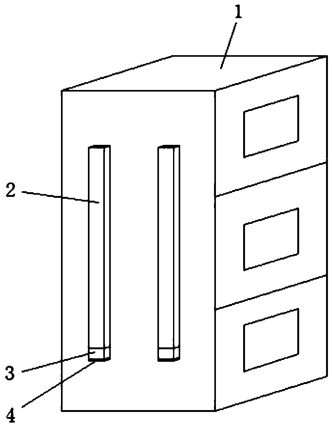
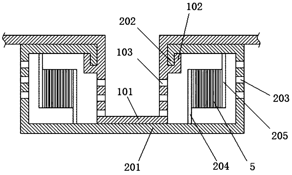
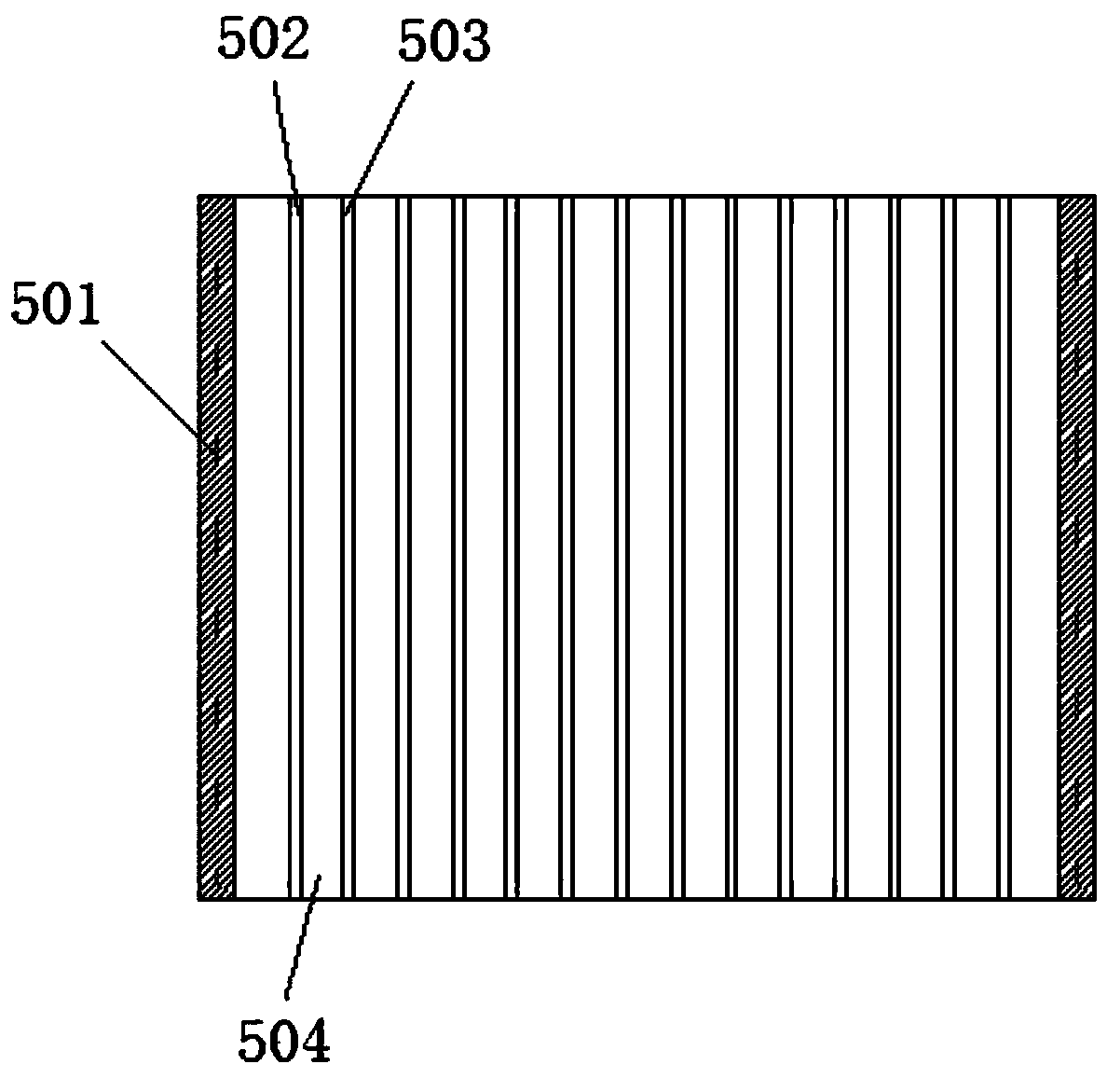
[0026] see Figure 1-5 As shown, this embodiment is a dust-proof and pressure-relieving device for an electrical switchgear, including a sealed cabinet body 1 , a dust-proof cover 2 , a dust-collecting seat 3 , a cover plate 4 and an electrostatic precipitator 5 .

[0027] The sealed cabinet body 1 is located on at least one side plate and is provided with several protruding tubes 101 with a U-shaped cross section. The mouth is closed, and a plurality of inner ven...


PUM


Abstract

The invention discloses a dust-proof pressure relief device of an electric switch cabinet, which comprises a sealed cabinet body, a dust-proof cover, a dust collecting seat, a cover plate and an electrostatic precipitator. The sealed cabinet body is provided with a protruding pipe with a first hook part and an inner ventilation hole. The dust cover comprises a cover body with a second hook part and an outer ventilation hole, , and an electrostatic precipitator is supported between a first baffle plate and the second baffle plate in the cover body; The electrostatic precipitator comprises a frame, a positive electrode plate and a negative electrode plate, wherein the positive electrode plate and the negative electrode plate are arranged spaced apart and a passage is left between adjacent electrode plates; The lower end of the dust cover is provided with a dust collecting seat, the dust collecting seat comprises a seat body, two sleeves are arranged in the seat body, and a multi-layer conical bucket with a dust outlet is arranged at the lower part of the sleeve cavity. On the basis of retaining the labyrinth channel, the invention increases the whole number of ventilation holes, so that the ventilation holes can meet the rapid release of air pressure; An electrostatic precipitator is added for dust removal, and dust falls into the dust collector seat. The conical bucket can prevent air flow inrush and prevent dust from entering the switch cabinet under the action of negative pressure.

Description

technical field [0001] The invention relates to the technical field of electrical control equipment, in particular to a dust-proof and pressure-relieving device for an electrical switch cabinet. Background technique [0002] The switch cabinet is a kind of electrical control equipment. The outside line first enters the main control switch in the cabinet, and then enters the sub-control switch. Each branch is set according to its needs. Since the electrical components in the switchgear will heat up during operation, the temperature and humidity in the switchgear will increase. In order to ensure the normal operation of the original components in the switchgear, the moisture in the switchgear needs to be discharged. The usual method is to add cooling vents to the cabinet body, but setting vent holes will reduce the protection level of the switch cabinet, and the dust from the external environment will easily enter the switch cabinet to form pollution, resulting in a decline in...

Claims


Application Information

Patent Timeline
IPC IPC(8): H02B1/30H02B1/28H02B1/56
CPCH02B1/28H02B1/30H02B1/565Y02A50/2351
Inventor 吴宏岐李小斌张帅帅
Owner BAOJI UNIV OF ARTS & SCI
Learn More