[0067] The accompanying drawing is the best embodiment of the mountain inspection route planning system, and the present invention will be further described in detail below in conjunction with the accompanying drawings.
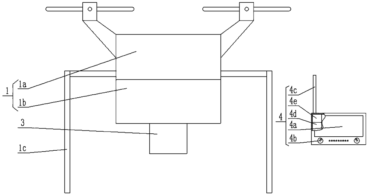
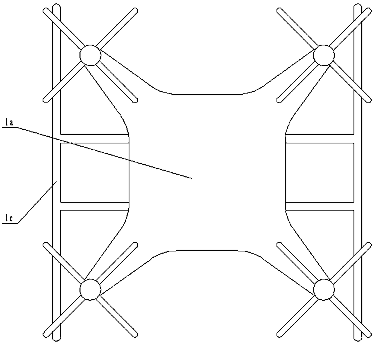
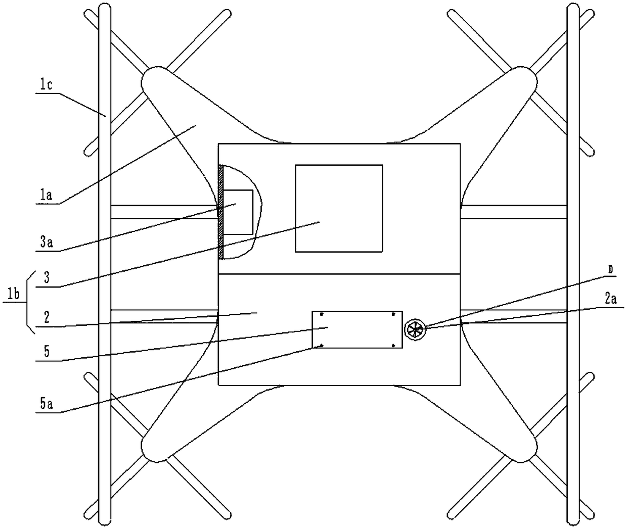
[0068] attached by figure 1 As shown, a mountain inspection route planning system includes an aircraft 1 and a control handle 4 . The aircraft 1 includes an unmanned aerial vehicle 1a, a hanger 1b installed on the belly of the unmanned aerial vehicle 1a, and landing supports 1c on both sides of the unmanned aerial vehicle 1a. The landing bracket 1c prevents the UAV 1a from colliding with the hanger 1b when it lands. attached by image 3 As shown, the hanger 1b includes a beacon transmitter module 2 and a topographic mapping module 3 .
[0069] attached by Figure 4 As shown, the bottom surface of the beacon emission module 2 is concaved with an electronic landmark storage room 2f, the left side of the electronic landmark storage room 2f is provided with a spring cavity 2f1, and the top surface of the electronic landmark storage room 2f has a limited concave. Position slideway 2g, electronic position mark storage room 2f right side is provided with throwing room 2f2. The electronic marker storage room 2f and the delivery room 2f2 are provided with an electronic marker 6, the inside of the delivery room 2f2 can only be provided with one electronic marker 6, and the lower part of the delivery room 2f2 is provided with a penetrating electronic marker delivery hole 2a. The above-mentioned electronic marker delivery hole 2a is provided with a rubber shielding group 2a1, which is attached Figure 8 As shown, the rubber shielding group 2a1 is surrounded by 3-6 pieces of fan-shaped rubber.
[0070] attached by Figure 5 As shown, the shape of the electronic marker 6 is the same as that of the bullet whose upper part is cylindrical and the lower part is conical. A counterweight 6a is arranged inside the tapered end of the electronic marker 6, and the counterweight 6a is made of metal with high density. For example, stainless steel or copper, so that the tapered end is guaranteed to face vertically downward during the descent of the electronic marker 6 . The interior of the cylindrical end of the electronic landmark 6 is sequentially provided with a power supply unit II 6b, a position tracker 6c and a light 6f from bottom to top, and the position tracker 6c has a wireless signal sending module. The position tracker is also called the positioning tracker, which can be positioned by GPS or Beidou system, and has the same principle and component composition as the shared bicycle positioning device. The position tracker 6c is provided with an antenna II 6c1, and a transparent belt 6e is inlaid on the circumferential surface corresponding to the electronic marker 6 and the lamp 6f, and the light can pass through the transparent belt 6e to irradiate to the outside. A touch switch 6d is provided on the cylindrical peripheral surface of the mark 6, and the position tracker 6c, the lamp 6f, the touch switch 6d and the power supply unit II 6b are connected in series.
[0071] The inside of the spring cavity 2f1 is provided with a thrust spring 15, the right side of the thrust spring 15 is provided with a push plate 14, the upper end of the push plate 14 is provided with a limit slider 14a, and the limit slider 14a Sliding is located at the limit slideway 2g inside. The limit slide 2g limits the sliding distance of the limit slide 14a. When the limit slide 14a is located at the leftmost end of the limit slide 2g, the push plate 14 is located inside the spring chamber 2f1. When the limit slide 14a is located at the limit slide When the rightmost end of the track 2g, the right end face of the push plate 14 is located at the far right side of the electronic marker storage room 2f. In order to increase the contact area between the push plate 14 and the electronic marker 6 and improve the frictional force, the right end surface of the push plate 14 is an arc-shaped surface matching the cylindrical end surface of the electronic marker 6 .
[0072] Simultaneously, the cross-section of the right end face of the delivery chamber 2f2 is also semicircular, and the radius of the cross-section of the right end face is the same as the radius of the cylindrical end face of the electronic marker 6. The right side of the delivery chamber 2f2 is provided with a telescopic solenoid valve 11, and the The valve stem of the retractable solenoid valve 11 corresponds to the touch switch 6d. Telescopic solenoid valve 11 is made up of valve stem, electromagnet and spring, and when telescopic solenoid valve 11 is energized, valve stem overcomes spring thrust recovery, and when telescopic solenoid valve 11 is deenergized, electromagnet loses magnetism, and spring pushes valve stem to eject.
[0073] attached by Figure 5 As shown, the infrared transmitter 16 and the infrared receiver 16a are respectively arranged on the front and rear ends of the electronic marker storage room 2f and the delivery room 2f2. The number of electronic markers 6 inside the marker storage room 2f and the delivery room 2f2 is the same, and the distance between two adjacent infrared emitters 16 is the same as the width of the electronic markers 6 . The electronic marker 6 blocks the infrared emitter 16 and the infrared receiver 16a, and every time an electronic marker 6 is dropped, the push plate 14 pushes the electronic marker 6 to the right under the thrust of the thrust spring 15, and an infrared receiver 16a is added to receive How many electronic markers 6 have been put in altogether can be known by the number of infrared signals received, and how many electronic markers 6 are left in the electronic marker storage room 2f.
[0074] attached by image 3 As shown, a cover plate 5 is covered under the electronic marker storage room 2f, and the cover plate 5 is fixedly connected to the bottom surface of the marker transmitting module 2 through bolts 5a. Attached Figure 5 As shown, there are two obliquely symmetrical rollers 5b arranged above the cover plate 5, and the tapered end of the electronic marker 6 is sandwiched between the two rollers 5b and is in contact with the rollers 5b. The interior of the roller 5b is pierced with an intermediate shaft 5c along its axial direction, the lower end of the intermediate shaft 5c is pierced to the inside of the cover plate 5, and the upper and lower ends of the intermediate shaft 5c are respectively provided with a limiting block 5c1. The lower limit block 5c1 prevents the intermediate shaft 5c from detaching from the cover plate 5, and the upper end limit block 5c1 prevents the roller 5b from detaching from the intermediate shaft 5c.
[0075] The left side of the electronic marker storage room 2f is provided with a vertical air passage 2c, and the bottom of the vertical air passage 2c is connected with an air inlet 2b, and the air inlet 2b connects the vertical air passage 2c with the outside of the marker transmitter module 2. An air compressor 12 is arranged inside the air inlet passage 2b, an air filter 13 is arranged at the air inlet of the air compressor 12, and an air outlet of the air compressor 12 is connected through the vertical air passage 2c.
[0076] A main air chamber 2d is provided above the electronic marker storage room 2f, the upper end of the vertical air passage 2c is connected with the main air chamber 2d, and the right side of the vertical air passage 2c is provided with a main air chamber 2d. The connected bypass airway 2c1, the opening of the bypass airway 2c1 in the main air cavity 2d is located on the right side of the vertical airway 2c. The middle part of the top surface of the main air chamber 2d is concaved with a pressure measuring air chamber 2d1, the inside of the pressure measuring air chamber 2d1 is provided with an electronic pressure sensor 8, and the left side of the main air chamber 2d is fixed with a sponge pad 2d4, The left side of the sponge pad 2d4 is provided with an auxiliary electromagnet 10a, and the right side of the sponge pad 2d4 is provided with a magnet 9 that slides freely along the axis of the main air chamber 2d. When the magnet 9 is in contact with the sponge pad 2d4, the magnet 9 is located in the vertical airway 2c opening left. The distance between the opening of the vertical air passage 2c and the opening of the bypass air passage 2c1 is greater than the length of the magnet 9 .
[0077] A retaining ring 2d2 protrudes from the end surface of the main air chamber 2d located on the left side of the high-pressure air passage 2e, and a buffer pad 2d3 is provided on the left end surface of the retaining ring 2d2. The magnet 9 moves to the right and impacts on the buffer pad 2d3, and the buffer pad 2d3 effectively absorbs the energy generated by the impact of the magnet 9 to avoid damage to the magnet 9.
[0078] The right end of the main air chamber 2d is vertically provided with a through-connected high-pressure air passage 2e, the high-pressure air passage 2e is located directly above the electronic position mark delivery hole 2a, and an electric butterfly valve is arranged inside the high-pressure air passage 2e 7.
[0079] An electromagnet 10 is provided on the right side of the main air cavity 2d, and a central processing unit III 17 with a wireless transceiver function is provided inside the beacon transmitter module 2 . Electric butterfly valve 7, electronic pressure sensor 8, electromagnet 10, auxiliary electromagnet 10a, retractable solenoid valve 11, air compressor 13, infrared emitter 16 and infrared receiver 16a are electrically connected to central processing unit III17 respectively.
[0080] The panel of the operating handle 4 is inlaid with a display 4a and a control button 4b, the operating handle 4 is provided with an antenna I4c, and the operating handle 4 is provided with a central processing unit II4d with a wireless transceiver module and a power supply unit I4e. The display 4a, the control buttons 4b, the antenna I4c and the power supply I4e are respectively electrically connected to the central processing unit II4d.
[0081] The topographic surveying and mapping module 3 is internally provided with a central processing unit I3a with a wireless transceiver module, and the topographic surveying and mapping module 3 adopts an airborne LIDAR system.
[0082] The airborne LIDAR system is laser detection and measurement, also known as laser radar. It is an airborne laser scan using GPS and an IMU (inertial measurement unit). The measured data is the discrete point representation of the digital surface model, and the data contains spatial three-dimensional information and laser intensity information. The digital elevation model can be obtained and the height of the ground cover can be obtained at the same time.
[0083] Airborne LIDAR is an active earth observation system, a new technology first developed by western countries and put into commercial application in the early 1990s. It integrates laser ranging technology, computer technology, and inertial measurement unit (IMU)/DGPS differential positioning technology. A brand new technical means. It has the characteristics of high degree of automation, less affected by weather, short data production cycle and high precision. The laser pulses emitted by the airborne LIDAR sensor can partially penetrate the shelter of trees to directly obtain high-precision three-dimensional surface terrain data.
[0084] System composition
[0085] The airborne LIDAR system mainly includes: 1. Dynamic differential GPS receiver, used to determine the spatial position of the scanning projection center; 2. Attitude measurement unit (IMU), used to measure the spatial attitude parameters of the main optical axis of the scanning device; 3. Laser A scanning ranging system is used to measure the distance from the sensor to the ground point; 4. A set of imaging device (mainly a digital camera) is used to obtain the color digital image corresponding to the ground for the final production of the orthophoto.
[0086] Principle of Laser Scanning Ranging System
[0087] Radio waves, X-rays, visible light, infrared light, etc. are all electromagnetic waves. In radar, after the radio wave sent by the transmitter is shot into the air, part of it is reflected by objects or air, and is received by the radar receiver system. Radar distance. Lidar uses infrared, or visible, or ultraviolet light emitted by lasers. The basic principle of laser ranging is to use the propagation speed of light in the air to measure the time for the light wave to travel back and forth on the measured distance to obtain the distance value. Assuming that the time for the light wave to travel back and forth over a certain distance is t, the distance to be measured can be expressed as D=1/2ct. In the formula (1), c is the propagation speed of the light wave in vacuum, which is about 300000km/s. The distance D can be obtained only by obtaining the time accurately.
[0088] The specific implementation methods include pulse method, phase method and frequency conversion method, and the pulse method and phase method are commonly used. The phase method indirectly determines the propagation time by measuring the phase difference of a continuous wave (CW) signal; the pulse method directly measures the propagation time of the pulse signal. If the surface of the object is uneven, use a 3D laser scanner on the ground to obtain a surface topography map of the reflective object; use an airborne lidar system to obtain a high-precision digital contour map.
[0089] The internal power supply device of the UAV 1a provides the required power for the internal devices of the beacon transmitting module 2 and the internal devices of the topographic mapping module 3 .
[0090] The central processing unit I3a and the central processing unit III17 are respectively connected with the central processing unit II4d through wireless signals.
[0091] A method for using a mountain inspection route planning system, comprising the following steps:
[0092] Step 1, terrain mapping and path selection:
[0093] Let the aircraft 1 fly, and use the terrain mapping module 3 to survey and map the terrain between the starting point of the staff and the power tower that needs to be inspected, and transmit the surveying and mapping data to the control handle 4, and display it on the display 4a.
[0094] Through the surveying and mapping results, you can observe the direction of the mountain, the distribution of rivers and the density of the forest. According to the surveying and mapping data, select a route with a gentle mountain trend, no river or narrow river surface, and loose forest, and mark the route through satellite positioning;
[0095] Step 2, release electronic markers:
[0096] After the route is selected, an electronic marker 6 is placed on the route at intervals of 800-1500m to help the staff ensure that they are moving along the route, or make corrections after deviation from the route.
[0097] Before putting in the electronic position marker 6, the telescopic solenoid valve 11 is powered off, the valve stem head moves forward under the push of the spring and hits the touch switch 6d, the position tracker 6c and the light 6f start to work, and then the telescopic solenoid valve 11 is powered on, and the valve stem retracts. back.
[0098] The central processor III 17 controls the work of the air compressor 12 to increase the internal air pressure of the main air cavity 2d, and the electronic pressure sensor 8 monitors the internal air pressure of the main air cavity 2d in real time. When the internal air pressure of the main air cavity 2d reaches a specified value, the central processing unit III17 controls the stop of the air compressor 12, the opening of the electric butterfly valve 7, and the change of the coil current direction of the electromagnet 10 and the auxiliary electromagnet 10a. Make the auxiliary electromagnet 10a and the magnet 9 repel each other, the electromagnet 10 and the magnet 9 attract each other, the air inside the air chamber 2d enters the high-pressure air channel 2e through the electric butterfly valve 7, and pushes the electronic marker 6 to be ejected through the electronic marker delivery hole 2a.
[0099] Because the auxiliary electromagnet 10a and the magnet 9 repel each other, the electromagnet 10 and the magnet 9 attract each other, so the magnet 9 pushes to the right along the main air cavity 2d, which acts as a piston and further improves the thrust of the air entering the high-pressure air passage 2e.
[0100] After the electronic marker 6 inside the delivery chamber 2f2 is ejected, the push plate 14 pushes the electronic marker 6 inside the electronic marker storage room 2f to the right under the thrust of the thrust spring 15 into the delivery chamber 2f2, and the infrared receiver 16 receives it. The incoming infrared signal increases by one. The central processing unit III 17 changes the coil current direction of the electromagnet 10 and the auxiliary electromagnet 10a again, so that the auxiliary electromagnet 10a and the magnet 9 attract each other, the electromagnet 10 and the magnet 9 repel each other, and the magnet 9 pushes to the left along the main air cavity 2d, and Impact energy is absorbed by the sponge pad 2d4;
[0101] Step 3, staff inspection:
[0102] The staff conducts inspections according to the planned route, and the electronic marker 6 will send a position signal and light, and the position signal of each electronic marker 6 will be displayed on the display 4a, so as to prevent the staff from deviating from the planned route.
[0103] After the inspection is completed, return along the planned route, recover the electronic marker 6 on the way back, then open the cover 5 below the electronic marker storage room 2f, and put the electronic marker 6 back into the electronic marker storage room 2f.
[0104] The embodiments of the present invention have been described in detail above in conjunction with the accompanying drawings, but the present invention is not limited to the above embodiments, and can also be made without departing from the gist of the present invention within the scope of knowledge possessed by those of ordinary skill in the art. Variations.