

Steel slag breaking sorting reuse system for iron and steel smelting processes
A recycling and process technology, applied in the field of steel slag crushing, sorting and recycling systems, can solve the problems of low manual screening efficiency, low work efficiency, high labor intensity, etc., to achieve reduced labor intensity, high work efficiency, and good crushing effect Effect
- Summary
- Abstract
- Description
- Claims
- Application Information
AI Technical Summary
Problems solved by technology
Method used
Image

Examples
Embodiment Construction
[0024] In order to make the technical means, creative features, goals and effects achieved by the present invention easy to understand, the present invention will be further described below in conjunction with specific illustrations. It should be noted that, in the case of no conflict, the embodiments in the present application and the features in the embodiments can be combined with each other.
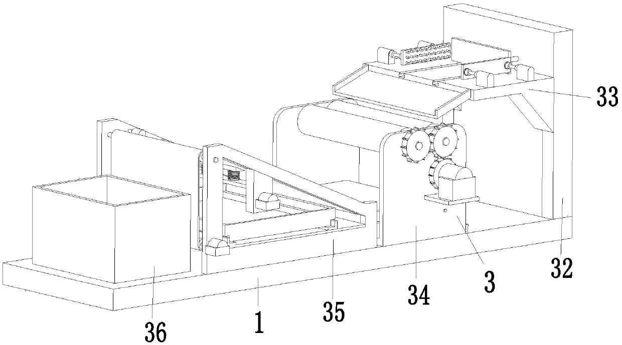
[0025] Such as Figure 1 to Figure 4 As shown, a steel slag crushing, sorting and reuse system for iron and steel refining process includes a bottom plate 1, a drum device 2 and a crushing device 3, and the upper end of the bottom plate 1 is equipped with a crushing device 3; The steel slag enters the crushing device 3, and the crushing device 3 can break the larger block of steel slag into smaller pieces, which is convenient to be made into building materials.
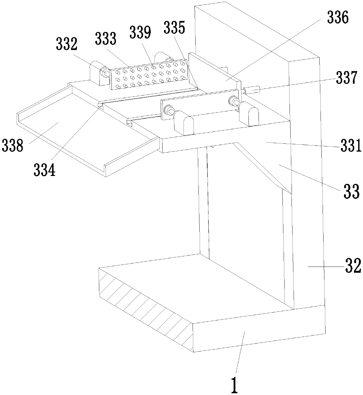
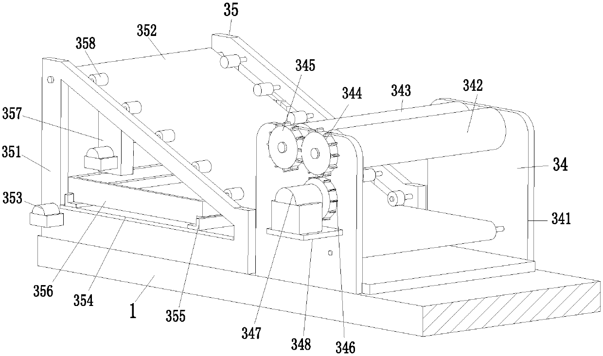
[0026]The crushing device 3 includes a support plate 32, a crushing mechanism 33, a milling mechanism 34, a vibrating scr...
PUM
 Abstract
Description
Claims
Application Information