Display device and display method
A display device and display method technology, applied in optics, lenses, instruments, etc., can solve problems such as inability to switch freely, poor user experience value, etc., and achieve the effects of reducing eye fatigue, increasing the selection range, and improving imaging quality.
- Summary
- Abstract
- Description
- Claims
- Application Information
AI Technical Summary
Problems solved by technology
Method used
Image

Examples
Embodiment 1
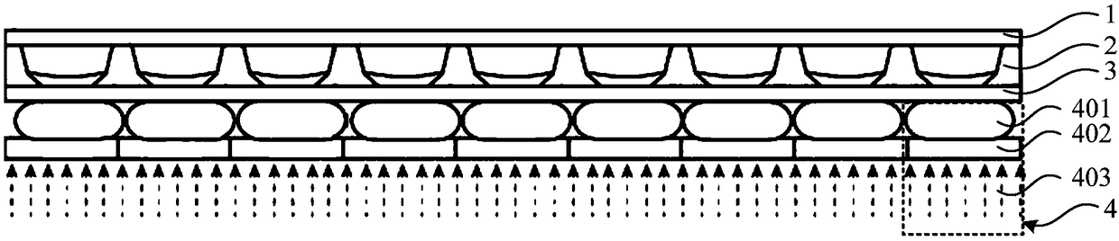
[0080] The present invention provides a display device, please refer to figure 1 , which is shown as a cross-sectional structure diagram of the display device, including an upper electrode layer 1, a base electrode layer 2, a lower electrode layer 3 and a plurality of light providing units 4, wherein the base electrode layer 2 is connected to the upper electrode layer 1 Below, the lower electrode layer 3 is connected under the base electrode layer 2 , and the light providing unit 4 is disposed under the lower electrode layer 3 .
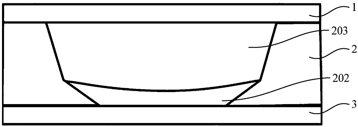
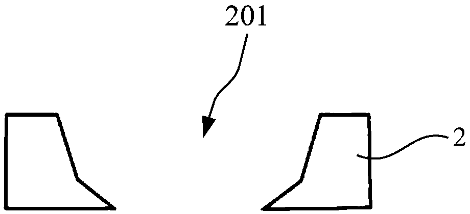
[0081] Specifically, the base electrode layer 2 includes a plurality of zoom liquid lens cavities that penetrate the base electrode layer 2 up and down, and the upper electrode layer 1, the base electrode layer 2 and the lower electrode layer 3 together form a zoom lens cavity. In the liquid lens array, each zoom liquid lens cavity corresponds to a zoom liquid lens unit, and the main body of the base electrode layer 2 serves as the base electrode of ...
Embodiment 2
[0102] The display device of the present invention can be applied to various devices with display functions, such as televisions, computers, mobile phones and the like. As an example, see Figure 12 , is shown as a structural schematic diagram of a mobile electronic device 6 using the display device of the present invention. The mobile electronic device 6 may be a notebook computer, and its display screen at least includes an LED backlight layer, a liquid crystal layer and a zoom Liquid lens layer. In this embodiment, the display device can also optionally be configured with an eye tracker 601, a distance sensor 602, a display camera 603, or a wearable camera 604, so as to use the eye tracker 601 to find the position of the observer's eyes and measure the distance between the eyes and the position of the observer. The distance between the display device, or use the display camera 603 and the distance sensor 602 to measure the distance between the observer's eyes and the displ...
Embodiment 3
[0110] This embodiment adopts basically the same technical solution as Embodiment 1, the difference is that the light providing unit of the display device in Embodiment 1 is based on liquid crystal display (LCD) technology, and in this embodiment, the light providing unit adopts Light-emitting diode (LED) technology.
[0111] As an example, see Figure 15 , Figure 16 and Figure 17 , the light providing unit includes a light emitting diode 404 and a thin film transistor 405 from top to bottom, and the thin film transistor 405 is used to control whether the light emitting diode 404 is on or off, wherein, Figure 15 It is shown that the display device of this embodiment presents a schematic diagram of 2D color display in the state where no voltage is applied to the metal electrodes Figure 16 It is shown as a schematic diagram of the 2D color display presented by the display device of the present embodiment in the state of applying a voltage to the metal electrodes, Figure...
PUM
 Abstract
Description
Claims
Application Information
 - R&D
- Intellectual Property
- Life Sciences
- Materials
- Tech Scout
- Unparalleled Data Quality
- Higher Quality Content
- 60% Fewer Hallucinations
Browse by: Latest US Patents, China's latest patents, Technical Efficacy Thesaurus, Application Domain, Technology Topic, Popular Technical Reports.
© 2025 PatSnap. All rights reserved.Legal|Privacy policy|Modern Slavery Act Transparency Statement|Sitemap|About US| Contact US: help@patsnap.com