
A system and method for station area topology identification based on power line broadband carrier (HPLC)

A broadband carrier and identification system technology, applied in the distribution line transmission system, information technology support system, electrical components, etc., can solve the problems of untimely update files, manual input update, inconsistency, etc., to facilitate intelligent operation and maintenance business, The effect of improving the quality of power supply

Active Publication Date: 2019-01-22
SHIJIAZHUANG KE ELECTRIC
View PDF4 Cites 36 Cited by
  • Summary
  • Abstract
  • Description
  • Claims
  • Application Information

AI Technical Summary

Problems solved by technology

[0003] At present, the topological relationship of the power network in the distribution substation area mainly relies on the topology data left over from the construction of the substation area. In this way, manual entry of files is required during the initial installation, and the workload is huge. In the later stage, if equipment replacement or line changes occur, manual entry is also required. renew
In actual use, there are often entry errors or untimely update files, resulting in inconsistencies between the actual distribution network topology and the main station display

Method used


Image

  • A system and method for station area topology identification based on power line broadband carrier (HPLC)
  • A system and method for station area topology identification based on power line broadband carrier (HPLC)
  • A system and method for station area topology identification based on power line broadband carrier (HPLC)

Examples


Embodiment Construction

[0044] The present invention will be further described below in conjunction with accompanying drawing.

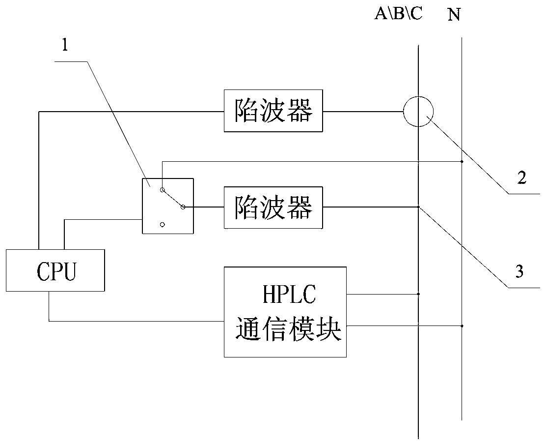
[0045] The present invention proposes a station area topology identification system composed of a signal sending device and a signal receiving terminal. The signal sending device is installed at the root of the transformer, and the signal receiving terminal is matched with the branch box and the meter box of the station area, and installed on the incoming or outgoing line. Due to the simple wiring at the incoming line end, it is recommended to install it at the incoming line end.

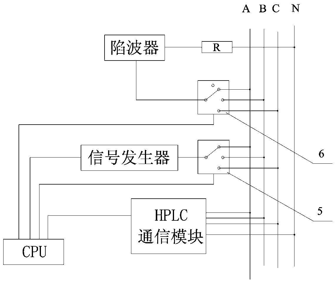
[0046] see figure 2 , the signal sending device includes a CPU and supporting circuits, a communication module, a signal generator, and a signal generator selection switch 5, the communication module is a power line broadband carrier (HPLC) communication module, and the CPU controls the signal generator selection switch 5 to connect the signal generator to On the A, B or C phase of the three-ph...


PUM


Abstract

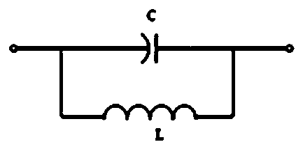
The system and method of station area topology identification based on power line broadband carrier (HPLC) relate to a distribution transformer station area network topology identification technology,in particular to a method of distribution network topology automatic identification system using power line broadband carrier (HPLC) as a communication means, which is used for automatic identification of station area topology. The system consists of a signal transmitting device and a signal receiving terminal. The signal transmitting device includes a power line broadband carrier (HPLC) communication module installed at the root of the transformer. The signal receiving terminal has built-in trap to block the 50Hz signal, and has a unique ID code for the whole network through the specific frequency signal, and is installed at the inlet or outlet terminal of the branch box and the meter box. The signal transmitting device first obtains the ID codes of all signal receiving terminals, transmits signals, controls the states of the signal receiving terminals, detects the current direction, automatically identifies the parent nodes of each branch box and the meter box according to the current direction, and thus obtains the topology diagram of the whole station area. In the implementation process of the invention, the terminal device does not need to be configured with parameters, the HPLC is used as a communication means, no extra wiring is needed, the communication advantage of the HPLC is fully utilized, and the identification process is realized quickly and accurately.

Description

technical field [0001] The invention relates to an identification technology of a power grid topology in a distribution transformer area, in particular to a method for an automatic identification system of a distribution network topology structure using a power broadband carrier (HPLC) as a communication means. Background technique [0002] Distribution network topology is the basis for distribution automation. In the process of new construction, expansion, operation and maintenance of smart substations, changes in distribution equipment in the distribution network will lead to changes in the topological relationship of the distribution network in the station area. In order to improve the quality of power supply, it is necessary to grasp the network topology relationship of "transformer-branch box-meter box" of the entire station network system in real time. [0003] At present, the topological relationship of the power network in the distribution substation area mainly rel...

Claims


Application Information

Patent Timeline
IPC IPC(8): H02J13/00H04B3/54
CPCH04B3/54H02J13/00007Y02B90/20Y04S40/121
Inventor 李春海李建凯陈贺刘立锋王诚高军利孔江涛沈占辉常生强芦斌何世鹏刘晓龙崔振伟郝立佳李永津支智勇刘朋飞刘海涛李峥安志国吴纳磊王志辉王强高胜国翟志国张奎仲张向平张权王欣胡金路
Owner SHIJIAZHUANG KE ELECTRIC
Learn More