
Efficient tea screening device

A screening device and high-efficiency technology, applied in the field of high-efficiency tea screening devices, can solve the problems of uneven distribution of tea screening size, poor tea separation effect, low screening efficiency, etc. Small footprint and simple structure

Inactive Publication Date: 2019-01-25
赖小琴
View PDF1 Cites 3 Cited by
  • Summary
  • Abstract
  • Description
  • Claims
  • Application Information

AI Technical Summary

Problems solved by technology

This invention solves the problem that the size distribution of tea leaves is not uniform due to the large amount of feed, resulting in poor separation effect of tea leaves
However, this invention does not solve the problems of low sieving efficiency and incomplete sieving caused by the accumulation of tea leaves

Method used


Image

  • Efficient tea screening device
  • Efficient tea screening device
  • Efficient tea screening device

Examples


Embodiment 1

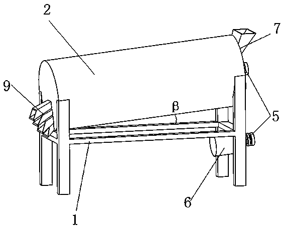
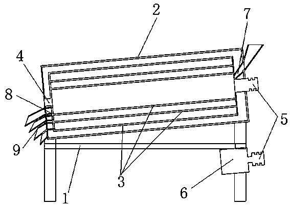
[0028] Such as Figure 1~2 As shown, a high-efficiency tea screening device includes a frame 1, an inclined screening cylinder 2, and a plurality of screen cylinders 3 that are installed in the screening cylinder 2 and coaxially arranged in sequence, and are connected inside and outside. The screening cylinder 2 is fixedly mounted on the frame 1, and one end of the screen cylinder 3 is rotatably mounted on the frame 1 through a rotating shaft 4, and the rotating shaft 4 is rotatably mounted in the center of the screening cylinder 2. At the axis, the other end is connected with a drive motor 6 through a belt (not shown in the figure) and a pulley 5. The drive motor 6 is installed on the frame 1, and the multi-layered screen cylinder 3 has a mesh aperture from the inside to the outside. Decrease in turn, the upper end of the innermost screen cylinder 3 is provided with a feed port 7 leading to the outside of the screen cylinder 2, and the bottom of the screen cylinder 2 and each...

Embodiment 2

[0036] The technical solution of this embodiment is basically the same as that of Embodiment 1, the difference is that:

[0037] In this embodiment, at one end of the screen cylinder 3 , only the innermost screen cylinder 3 is fixedly connected to the rotating shaft 4 .

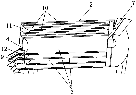
[0038] Such as image 3 As shown, each sieve cylinder 3 is provided with a baffle 10 fixedly connected to the sieve cylinder 2 to prevent the tea leaves from falling back into the relatively inner sieve cylinder 3 when they are turned over in the sieve cylinder 3. Screening efficiency.

[0039] Such as Figure 3~4 As shown, in order to facilitate the installation of the baffle plate 10, one end of the screen cylinder 3 is all fixed on the rotating shaft 4, and the other end is a through-hole 11 extending along its axial direction except for the innermost screen cylinder 3. , the baffle plate 10 extends into the screen cylinder 3 along the through opening 11, one end of the baffle plate 10 is fixedly connec...


PUM


Abstract

The invention discloses an efficient tea screening device. The device comprises a rack, a screening cylinder and multiple screen cylinders, wherein the screen cylinders are coaxially arranged and sequentially sleeved with one another from inside to outside; the screening cylinder is fixedly mounted on the rack, one end of each screen cylinder is rotatably mounted on the rack through a rotating shaft, the apertures of mesh holes of the multiple layers of screen cylinders are sequentially decreased from inside to outside, a feeding port communicated with the exterior of the screening cylinder isformed in the upper end of the innermost screen cylinder, and discharge openings communicated with the exterior of the screening cylinder are formed in the bottoms of the lower ends of the screeningcylinder and screen cylinders respectively. No vibration is caused, the operation is stable, the noise is small, and the service life of the device is long; compared with the traditional tea circularscreening machines, the tea screening device has the advantages of being simple in structure, small in occupied space, high in screening speed and efficiency and large in working load; meanwhile, teascreening is conducted from inside to outside, the screening effect is great, and the efficiency is high.

Description

technical field [0001] The invention belongs to the technical field of tea processing equipment, in particular to a high-efficiency tea screening device. Background technique [0002] After the tea is picked, drying and screening are generally carried out. The drying process is to remove the moisture in the tea, which has the characteristics of improving the aroma of the tea and increasing the storage time of the tea. The screening is to increase the commodity value of the tea. Standardize the quality of tea. Existing tea sieving is usually carried out by using a tea screening machine. When the tea is sieved, after the tea is placed on the sieve plate, the vibration device is used to drive the sieve plate to vibrate up and down, and the tea powder and tea stems in the tea leaves It falls from the sieve holes of the sieve plate to complete the sieving of tea powder and tea stems in the tea leaves. And because the existing tea screening machines are driven by the vibrating d...

Claims


Application Information

Patent Timeline
IPC IPC(8): B07B1/22B07B1/42A23F3/06
CPCB07B1/22A23F3/06B07B1/42B07B2201/04
Inventor 赖小琴
Owner 赖小琴
Learn More