
Blisk swing friction welding equipment and method

A technology of oscillating friction and integral blisks, which is applied in the direction of welding equipment, welding equipment, auxiliary welding equipment, etc., can solve the problems of vibration and deformation of long blades, and achieve the effect of high welding efficiency and welding position accuracy

Active Publication Date: 2019-01-25
AVIC BEIJING AERONAUTICAL MFG TECH RES INST
View PDF6 Cites 6 Cited by
  • Summary
  • Abstract
  • Description
  • Claims
  • Application Information

AI Technical Summary

Problems solved by technology

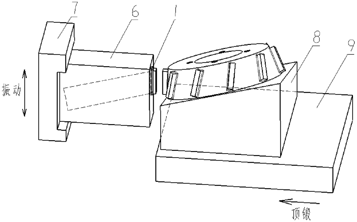
[0006] The embodiment of the present invention provides an integral blisk oscillating friction welding equipment and method, which allows the blade to move linearly under the action of upsetting force, and the blisk swings in a high-frequency angular direction, which can make the blade under the action of upsetting force and high-frequency welding. The friction welding of the swinging blisk solves the deformation problem caused by the vibration of the long blade when the whole blisk is welded

Method used


Image

  • Blisk swing friction welding equipment and method
  • Blisk swing friction welding equipment and method
  • Blisk swing friction welding equipment and method

Examples


Embodiment Construction

[0036] Embodiments of the present invention will be further described in detail below in conjunction with the accompanying drawings and examples. The detailed description and accompanying drawings of the following embodiments are used to illustrate the principles of the present invention, but cannot be used to limit the scope of the present invention, that is, the present invention is not limited to the described embodiments, without departing from the spirit of the present invention Any modification, substitution and improvement of parts, components and connection methods are covered under.

[0037] It should be noted that, in the case of no conflict, the embodiments in the present application and the features in the embodiments can be combined with each other. The present application will be described in detail below with reference to the accompanying drawings and embodiments.

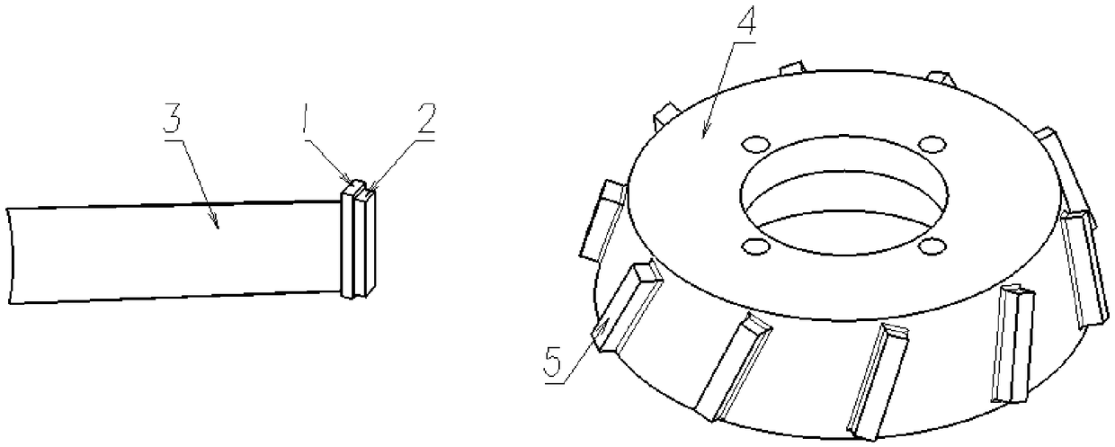
[0038] figure 2 It is a schematic diagram of the structure of the blade and the blisk before w...


PUM


Abstract

The invention relates to blisk swing friction welding equipment and method. The equipment comprises a base, a blade driving unit and a blisk driving unit, wherein the base is of a disc structure witha blisk as the center, and a plurality of blade driving mechanisms are arranged on the base; the blade driving unit comprises a blade clamp and an upsetting driving mechanism, the blade clamp is usedfor clamping blades, the blade clamp is provided with a through hole structure for clamping the blades, and the blades can penetrate through and be clamped in the through hole structure; the upsettingdriving mechanism is used for driving the blade clamp to drive the blades to move linearly relative to the base; the blisk driving unit comprises a blisk clamp and a swing driving mechanism, the blisk clamp is used for clamping the blisk, the blisk clamp is provided with a mounting surface for clamping the blisk, and the blisk and the blisk clamp are coaxially arranged in the center of the base;the swing driving mechanism is used for driving the blisk clamp to drive the blisk to swing in a preset angle range relative to the base.

Description

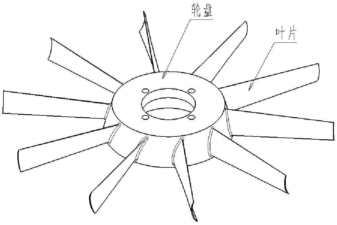
technical field [0001] The invention relates to the technical field of aviation manufacturing, in particular to an integral blisk swing friction welding equipment and method. Background technique [0002] The blisk is one of the key parts of the new engine, see figure 1 , a plurality of blades are manufactured as a whole with the central blisk. Linear friction welding is a pressure welding method, because of its high welding quality, it has become a typical technical method for manufacturing blisks. [0003] According to the characteristics of the linear friction welding process, design and manufacture the parts of the blade and blisk before welding. During linear friction welding, install the blade before welding in the corresponding blade fixture, and drive the high-frequency vibration of the blade fixture to drive the high-frequency vibration of the blade; install the blisk before welding on the corresponding blisk fixture, and drive The blisk clamp realizes the upsett...

Claims


Application Information

Patent Timeline
IPC IPC(8): B23K20/12B23K20/26B23K37/04
CPCB23K20/1245B23K20/126
Inventor 张田仓李辉季亚娟李菊
Owner AVIC BEIJING AERONAUTICAL MFG TECH RES INST
Learn More