Automatic molding device

A molding and mold technology, applied in the field of automatic molding equipment, can solve the problems of non-recyclable, increased production funds, material damage, etc., and achieve the effect of saving funds, improving utilization rate, and saving leftover materials

Pending Publication Date: 2019-01-25
浙江橡企科技有限公司
View PDF15 Cites 3 Cited by
  • Summary
  • Abstract
  • Description
  • Claims
  • Application Information

AI Technical Summary

Problems solved by technology

Then it is injected into the mold through the runner. Due to the high temperature, the rubber will undergo vulcanization during the process of injection into the mold, resulting in damage to the material itself, resulting in the material being unable to be recycled after one use, especially in mass production. A lot of waste will be generated, resulting in a lot of damage to the material, which greatly increases the cost of production

Method used


Image

  • Automatic molding device
  • Automatic molding device
  • Automatic molding device

Examples


Embodiment Construction

[0038] The present invention will be further described below with specific examples.

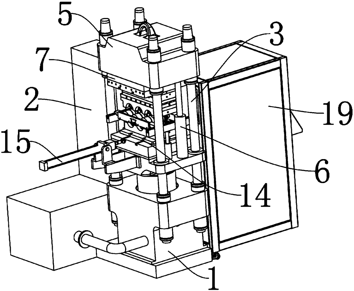
[0039] Such as figure 1 As shown, an automatic molding device includes a body 1, a control box 2 is arranged beside the body 1, the control box 2 is equipped with a PLC control system, a base 4 is arranged on the body 1, a guide column 3 is arranged on the body 1, and a guide column 3 is arranged on the body 1. There are four pillars 3 , the four guide pillars 3 are respectively arranged on the four corners of the base 4 , and the four guide pillars 3 all run through the base 4 . The upper mold beam 5 is slidably arranged on the guide pillar 3, and the upper mold beam 5 is provided with a sliding sleeve 23-2 which can slide on the guide pillar 3. The base 4 is provided with a first lifting part 6 connected to the upper mold beam 5, the first lifting part 6 is set as the first driving cylinder, and the first driving cylinder is set to two, and the two first driving cylinders are respectively...


PUM


Abstract

The invention discloses an automatic molding device. The molding device comprises a machine body and a control box disposed on the machine body. The machine body is provided with a base. The base is provided with a lower mold. The lower mold comprises a lower mold base, and the lower mold base is provided with a lower molding groove. A plurality of guiding columns are vertically disposed on the machine body, and an upper mold beam is disposed on the guiding columns in the sliding mode. An upper mold is connected to the mold beam, and the upper mold includes a runner plate provided with a plurality of hot runners, a cold runner plate provided with a plurality of cold runners, a heat insulation plate, an upper heating plate and an upper mold base. The mold base is provided with an upper molding groove, and the upper molding groove and the lower molding groove are matched to form a forming cavity. The upper mold is provided with an injection nozzle communicated with the forming cavity, the injection nozzle is in communication with the hot runners on the runner plate, and the base is provided with a first lifting portion for driving a molded material to break away from the upper mold.The automatic molding device has the advantage of improving the cyclic utilization rate of rubber molded materials.

Description

technical field [0001] The invention relates to the technical field of mechanical manufacturing automation, in particular to an automatic molding device. Background technique [0002] The production process of rubber products is quite complicated. The production process of rubber products is quite complicated. Before all production work, it is necessary to prepare raw materials, including mastication and mixing. Then it is injected into the mold through the runner. Due to the high temperature, the rubber will undergo vulcanization during the process of injection into the mold, resulting in damage to the material itself, resulting in the material being unable to be recycled after one use, especially in mass production. A large amount of waste will be generated, resulting in a large amount of damage to the material, which greatly increases the cost of production. Contents of the invention [0003] The object of the present invention is to provide an automatic molding device...

Claims


Application Information

Patent Timeline
Patent Type & Authority Applications(China)
IPC IPC(8): B29C45/42B29C45/43B29C45/72B29C45/17
CPCB29C45/17B29C45/42B29C45/43B29C45/72
Inventor 杨再金
Owner 浙江橡企科技有限公司
Why Eureka
Try Eureka