Cell phone cover plate screen printing device

A cover wire and cell phone technology, applied in printing devices, screen printing, printing, etc., can solve the problems of unsuitable high-efficiency models, high cost of vacuum suction cups, increased waste of resources, etc., to increase the success of screen printing Probability, convenient and simple disassembly and assembly, and the effect of improving work efficiency

Inactive Publication Date: 2019-01-25
江苏宇天港玻新材料有限公司
View PDF1 Cites 0 Cited by
  • Summary
  • Abstract
  • Description
  • Claims
  • Application Information

AI Technical Summary

Problems solved by technology

[0002] Judging from the current screen printing methods of mobile phone covers, most of the screen printing of mobile phone covers are fixed on the surface of the screen printing machine, and printed one by one by the machine. Most of the positioning methods use limit grooves or vacuum suction cups. However, the use of vacuum suction cups is costly and difficult to maintain. The tanks are often connected to the silk screen base, and the method of printing one piece at a time is not suitable for the high-efficiency mode of in-factory operations;
[0003] In the mobile phone cover screen printing device disclosed in the patent document CN201620971059.X, it solves the problem of low printing efficiency by setting up multiple processing stations, and also sets up a pick-up hole to facilitate picking up the workpiece. The processing stations set up by the former are all compatible with the mobile phone cover, but a factory often manufactures different types of covers, and there will be different sizes of covers that need to be processed. This device only provides one type of cover. It is convenient. When processing other types of cover plates, people often need to make new devices, which will increase the waste of resources, and the device may be disassembled and replaced many times. Unnecessary damage may occur. The device will still be a lot of inconvenience

Method used


Image

  • Cell phone cover plate screen printing device
  • Cell phone cover plate screen printing device
  • Cell phone cover plate screen printing device

Examples


Embodiment 1

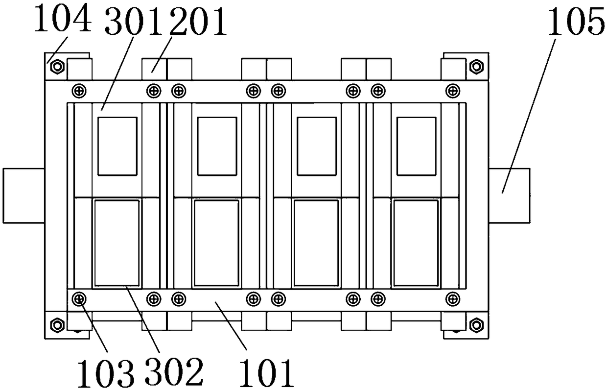
[0024] figure 1 As shown, a mobile phone cover screen printing device includes a screen printing seat plate 101 installed on the upper surface of the working table of the screen printing machine and hollowed out on the surrounding surface. The front and rear end hollow surfaces of the screen printing seat plate 101 are interspersed with multiple sets of No. 1 cards. Board 201 and No. 2 card board 202, No. 1 card board 201 and No. 2 card board 202 are matched one by one, the ends of No. 1 card board 201 and No. A No. 1 limiting plate 301 and a sitting wall 303 are closely placed in the gap between the plate 201 and the No. 2 clamping plate 202, and the upper middle part of the No. 1 limiting plate 301 and the No. 2 limiting plate 302 is provided with a limiting groove 304, and Both sides of the upper end of No. 1 limiting plate 301 and No. 2 limiting plate 302 are fixedly installed with sitting walls 303 stuck on the surface of No. 1 clamping plate 201 or No. 2 clamping plate 2...

Embodiment 2

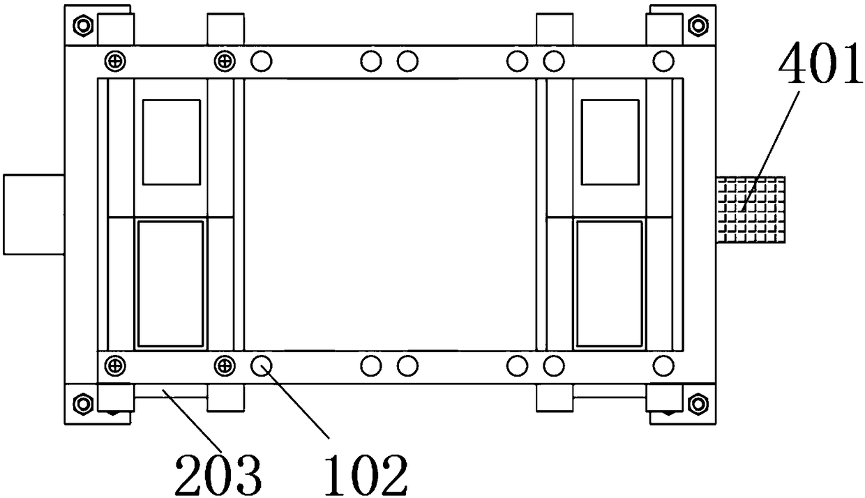
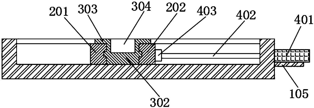
[0026] On the basis of above-mentioned embodiment 1, as figure 2 and image 3 As shown, people can release the fastening of the fixing screw 103, use bolts or the like to fix and install the cylinder part 401 on the surface of the cylinder placement plate 105, and punch holes on the corresponding side, and the assembly output rod 402 of the cylinder part 401 passes through the connecting block 403 It is fixedly connected with the No. 2 clamp 202, and the connection block 403 and the No. 2 clamp 202 can be bolted or glued. The connection mode between the connection block 403 and the output rod 402 is preferably threaded, that is, at the connection block 403 Threaded holes are drilled in the center, which is easy to do in the prior art. In this example, it should be noted that the assembly output rod 402 of the left and right cylinder parts 401 should not be installed on the supporting No. 1 pallet 201 and No. 2 pallet 202. superior,( figure 2 The structural diagram of the u...


PUM


Abstract

The invention relates to a cell phone cover plate screen printing device. The cell phone cover plate screen printing device comprises a screen printing base plate installed on the surface of a screenprinting machine working table and hollowed out in the upper surface and the peripheral surface. A plurality of first clamping plates and second clamping plates are inserted in the hollowed-out surfaces of the front end and the rear end of the screen printing base plate. The first clamping plates and the second clamping plates are matched with each other. The tail end of each first clamping plateand the tail end of each second clamping plate each penetrate out of the end face of the screen printing base plate. A first limiting plate and a sitting wall are closely placed in a gap between eachfirst clamping plate and the corresponding second clamping plate. The middle of the upper end of each first limiting plate and the middle of the upper end of each second limiting plate are each provided with a limiting groove. The two sides of the upper end of each first limiting plate and the two sides of the upper end of each second limiting plate are each fixedly provided with the correspondingsitting wall clamped on the surface of the corresponding first clamping plate or the corresponding second clamping plate. The cell phone cover plate screen printing device can be used multiple timesin combination, the work efficiency is greatly improved, the scratch and damage phenomenon probably happening during multiple times of taking can be reduced, and the screen printing success probability is increased.

Description

technical field [0001] The invention belongs to the technical field of glass screen printing technology, and in particular relates to a mobile phone cover screen printing device. Background technique [0002] Judging from the current screen printing methods of mobile phone covers, most of the screen printing of mobile phone covers are fixed on the surface of the screen printing machine, and printed one by one by the machine. Most of the positioning methods use limit grooves or vacuum suction cups. However, the use of vacuum suction cups is costly and difficult to maintain. The tanks are often connected to the silk screen base, and the method of printing one piece at a time is not suitable for the high-efficiency mode of in-factory operations; [0003] In the mobile phone cover screen printing device disclosed in the patent document CN201620971059.X, it solves the problem of low printing efficiency by setting up multiple processing stations, and also sets up a pick-up hole to...

Claims


Application Information

Patent Timeline
Patent Type & Authority Applications(China)
IPC IPC(8): B41F15/08B41F15/14B41F15/18B41F15/22B41F15/26
CPCB41F15/0804B41F15/14B41F15/18B41F15/22B41F15/26B41P2200/40B41P2215/10B41P2215/50B41P2217/60
Inventor 王进东
Owner 江苏宇天港玻新材料有限公司
Why Eureka
Try Eureka