A trolley bus power receiving system

A trolleybus and electric system technology, applied in the direction of electric vehicles, collectors, vehicle components, etc., can solve the problems of difficult operation, difficult adjustment, and time-consuming for the driver, so as to improve the efficiency of entering and exiting stations, save operating time, The effect of more charging time

Active Publication Date: 2019-01-25
ZHUZHOU ELECTRIC LOCOMOTIVE CO
View PDF5 Cites 1 Cited by
  • Summary
  • Abstract
  • Description
  • Claims
  • Application Information

AI Technical Summary

Problems solved by technology

[0005] Third, the charging current is large (800A)
[0009] The above method (1) needs to set up network cables above the road, which is not conducive to the beauty of the city; the mechanism designed in method (2) has high requirements for the accuracy of the trolleybus parking position, and the driver's operation is difficult, requiring the driver to operate the charger accurately and power supply rail contact
[0010] Moreover, a common defect of the above two methods is that the height of the charger from the ground is different when different stations are docked due to the uneven road surface. When charging, it is necessary to adjust the relative position between the charger and the power supply rail, which is difficult and expensive to adjust. time, which seriously affects the efficiency of vehicles entering and exiting the station

Method used


Image

  • A trolley bus power receiving system
  • A trolley bus power receiving system
  • A trolley bus power receiving system

Examples


Embodiment Construction

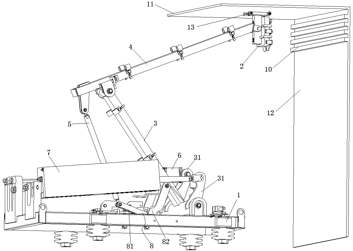
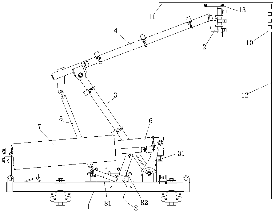
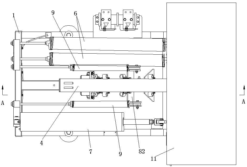
[0035] Such as Figure 1~4 As shown, a trolley bus power receiving system includes an underframe 1, a lower arm 3, an upper arm 4, a pull rod 5, a lifting bow drive device installed on the underframe 1, a bow charger 2, and a force transmission member 8 , balance spring 9.

[0036] The lower arm 3 is T-shaped, its cross bar is hinged with the underframe 1 , and the upper end of its vertical bar is hinged with the upper arm 4 . A plurality of ear plates 31 are fixedly arranged on the cross bar.

[0037] The lifting bow driving device is connected with the lower arm 3 and can drive the lower arm 3 to rotate around the hinge point between the lower arm 3 and the chassis 1 . The bow lifting device includes a bow lifting cylinder 7 and a bow lifting spring 6 . The bow raising cylinder 7 is installed on the underframe 1 . The piston rod of the bow-raising cylinder 7 is connected with the ear plate 31. One end of the lifting bow spring 6 is connected to the ear plate 31 , and th...


PUM


Abstract

The invention discloses a trolley bus power receiving system, wherein the lower end of a lower arm rod is articulated with a chassis, and the upper end is articulated with an upper arm rod; an upper end of that tie rod is articulate with a lower end of the upper arm rod; a bow head charger is arranged at the upper end of the upper arm rod; It also includes a force transducer and a balance spring.One end of the balance spring is hinged with the force transmitting member, and the other end is fixed on the chassis; a low end of that tie rod is articulated with a force transmit member, and the force transmitting member is articulate with a chassis; the invention also comprises a ceiling arranged horizontally, a side canopy arranged perpendicular to the ceiling, a power supply rail installed on the inner wall of the side canopy, and a bow head charger slidable along the ceiling. Before the bow charger abuts on the ceiling, the force transfer member is balanced by the pull rod and the balance spring, and does not rotate relative to the chassis. The invention requires low parking position accuracy of the driver, does not need to adjust the relative position of the bow head charger and the power supply rail, saves the operation time, leaves more charging time, improves the efficiency of the vehicle entering and leaving the station, and does not affect the appearance of the city.

Description

technical field [0001] The invention belongs to trolley bus technology, in particular to a trolley bus power receiving system. Background technique [0002] With the development of society, the concept of urban rail transit development such as energy saving and environmental protection has been continuously improved, and supercapacitor energy storage type trolleybuses have emerged as the times require. The so-called supercapacitor energy storage type trolleybus refers to the use of supercapacitors to store electric energy as power for traction, the use of the roof receiver system to receive and return current, and use the passengers to quickly complete charging within tens of seconds when getting on and off the platform. One charge can ensure that the supercapacitor energy storage type trolleybus runs to the next stop before charging. It is precisely because of the above characteristics that this model has been more and more popularized and used. However, the supercapacito...

Claims


Application Information

Patent Timeline
IPC IPC(8): B60L5/22B60L5/28B60L5/30
CPCB60L5/22B60L5/28B60L5/30
Inventor 林平张海丰张彦林冯叶熊玉玲
Owner ZHUZHOU ELECTRIC LOCOMOTIVE CO
Why Eureka
Try Eureka