A real-time communication control method for an unmanned vehicle

An unmanned vehicle and real-time communication technology, applied in the field of real-time communication control of unmanned vehicles, can solve the problems of transmission mechanism lag, prone to conflict, occupying bus resources, etc., so as to shorten the information interaction time and avoid information Conflict, the effect of reducing hardware cost

Inactive Publication Date: 2019-01-25
HUBEI UNIV OF AUTOMOTIVE TECH
View PDF8 Cites 5 Cited by
  • Summary
  • Abstract
  • Description
  • Claims
  • Application Information

AI Technical Summary

Problems solved by technology

[0007] In the prior art, the "idle" or "busy" state of the bus is unknown, and conflicts are likely to occur, resulting in signal errors;
[0008] When an error signal is generated, it will be resent, occupying a large amount of bus resources and even causing congestion;
[0009] (2) There is a serious lag in the transmission mechanism using priority arbitration, and the data cannot be effectively transmitted;
[0011] (4) The number of connectable nodes in the network is small, and the transmission rate is low;
[0012] (5) In the prior art, the bus with high real-time performance and better performance has high cost and limited application field
Since the development content of the early bus communication is for the early manned driving, it only needs to meet the transmission of the on-board electrical appliances, and there is no need to consider assisted driving and real-time performance. The hardware circuit design is relatively simple, and the number of network nodes is limited by physical characteristics; The software protocol is limited, and updates and iterations cannot be realized; if secondary development is required, the improvement will have little benefit and cannot meet the needs of future unmanned vehicles, so it is necessary to seek a new communication architecture

Method used


Image

  • A real-time communication control method for an unmanned vehicle
  • A real-time communication control method for an unmanned vehicle
  • A real-time communication control method for an unmanned vehicle

Examples


Embodiment Construction

[0040] In order to make the object, technical solution and advantages of the present invention more clear, the present invention will be further described in detail below in conjunction with the examples. It should be understood that the specific embodiments described here are only used to explain the present invention, not to limit the present invention.

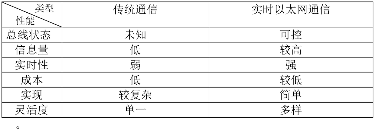
[0041] In the prior art, the "idle" or "busy" status of the bus is unknown, and conflicts are likely to occur, resulting in signal errors.

[0042] The application of the present invention will be further described below in conjunction with specific analysis.

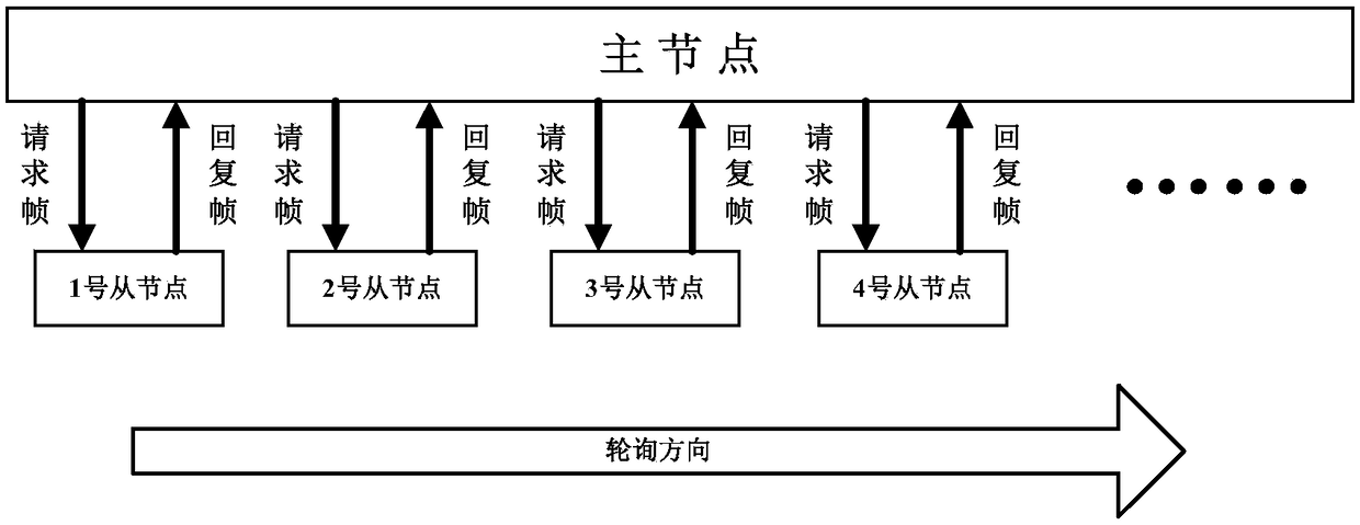
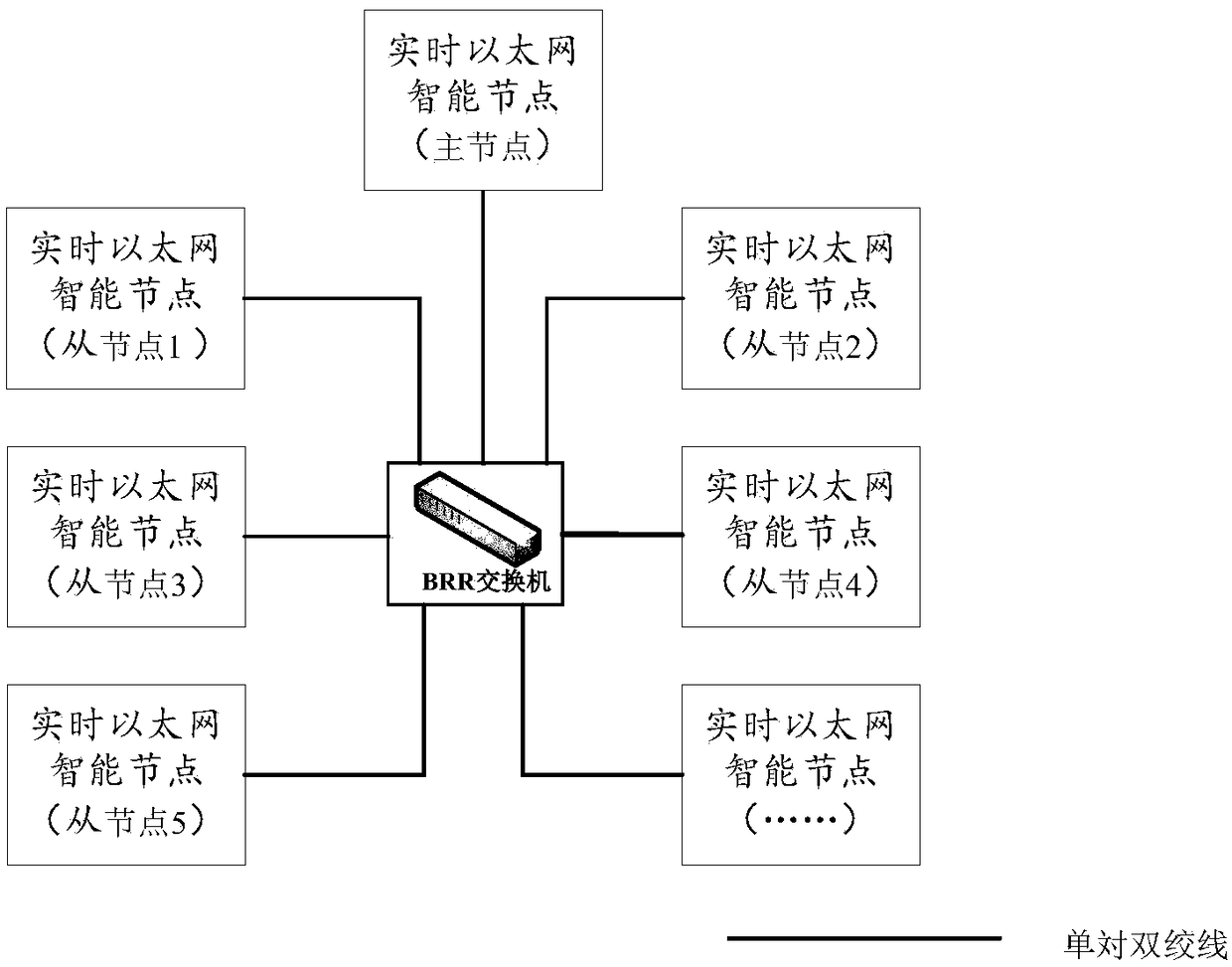
[0043]In the real-time communication control method for unmanned vehicles provided by the embodiment of the present invention, the network is composed of a plurality of real-time Ethernet intelligent communication nodes, and each real-time Ethernet intelligent communication node is interconnected by a single twisted pair and a switch , forming a real-time Ethernet v...


PUM


Abstract

The invention belongs to the field of vehicle unmanned driving, and discloses a real-time communication control method for unmanned vehicle. Each real-time Ethernet intelligent communication node is interconnected with an exchange through a single pair of twisted pair cables to form a real-time Ethernet vehicle network. At least one real-time Ethernet intelligent node existing in that network is amaster node, and each real-time Ethernet intelligent node is round-robin by unicast request frame in each communication cycle, each slave station is coordinated, bus usage right is allocated, and real-time communication is realized. The rest are configured as slave nodes, each node having a unique node number. The slave node sends a reply frame after receiving the request frame sent by the masternode, and broadcasts the data that it needs to send to the network. Each node in the network of the invention collects / transmits data once, so that the real-time performance will not be reduced evenin the face of increasing on-board sensors, and the network adapts to the development trend of future driverless vehicles.

Description

technical field [0001] The invention belongs to the field of unmanned vehicles, and in particular relates to a real-time communication control method for unmanned vehicles. Background technique [0002] At present, the existing technologies commonly used in the industry are as follows: [0003] Commonly used existing technologies in the industry include: LIN bus, CAN bus, FLERAY bus, and MOST bus; the LIN bus network is composed of a single master node and multiple slave nodes, the number of connectable nodes is small, and signals do not need to be arbitrated. The character length is long, the rate is up to 20kbps, and the transmission distance is short; the CAN bus network is composed of multiple nodes, and the arbitration method is used for communication. There are many nodes that can be connected, the real-time performance is low, and the rate is up to 1Mbps; The time-triggered communication method is adopted, which has high real-time performance, complicated implementat...

Claims


Application Information

Patent Timeline
Patent Type & Authority Applications(China)
IPC IPC(8): B60R16/023
CPCB60R16/0231
Inventor 兰建平钱毓铃周海鹰董秀娟邵俊
Owner HUBEI UNIV OF AUTOMOTIVE TECH
Why Eureka
Try Eureka