Worm gear transmission pumping unit and method

A worm gear and pumping unit technology, which is used in earth-moving drilling, fluid production, wellbore/well components, etc., can solve the problems of reduced transmission efficiency of the reducer, shortened service life of the pumping unit, and many transmission links of the reducer. , to achieve the effect of reducing transmission links, compact structure and improving energy efficiency

Active Publication Date: 2019-01-25
XI'AN PETROLEUM UNIVERSITY
View PDF10 Cites 3 Cited by
  • Summary
  • Abstract
  • Description
  • Claims
  • Application Information

AI Technical Summary

Problems solved by technology

Beam pumping units mostly use two-stage gear reducers. These reducers have many transmission links and large structural volume, and the transmission efficiency of the reducer will decrease accordingly; the crank-link mechanism realizes the reversing of the pumping unit. The momentary suspension point will produce a relatively large acceleration, which will lead to the unevenness of the movement of the donkey head; the beam pumping unit adopts a mechanical balance method, that is, the method of connecting the balance weight at the end of the beam, which will increase the pumping efficiency. reduce the energy consumption of the pumping unit and reduce the service life of the pumping unit
Due to its structural characteristics, the traditional beam pumping unit has disadvantages such as poor balance effect, large suspension point acceleration, large starting torque, low efficiency and large energy consumption.

Method used


Image

  • Worm gear transmission pumping unit and method
  • Worm gear transmission pumping unit and method
  • Worm gear transmission pumping unit and method

Examples


Embodiment Construction

[0027] Below in conjunction with accompanying drawing, the present invention is described in further detail:

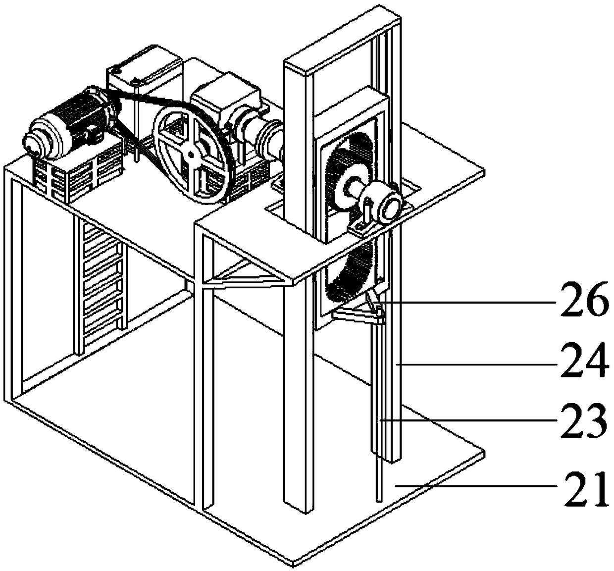
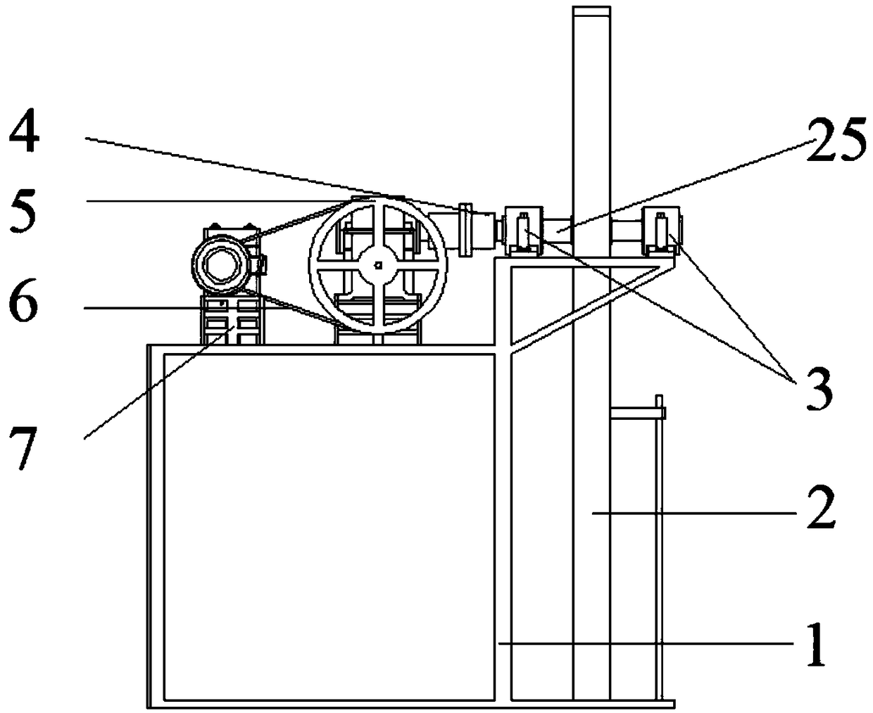
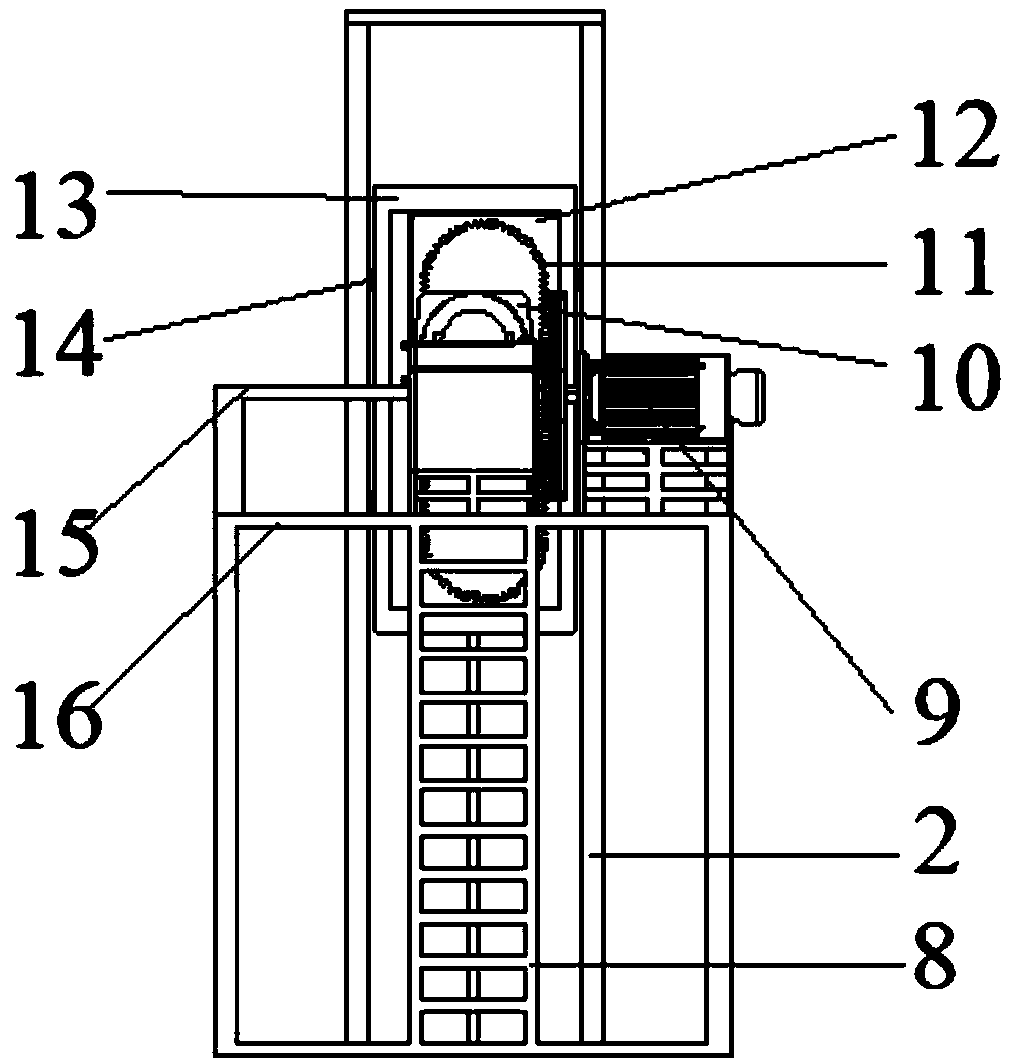
[0028] see Figure 1 to Figure 5 , a worm and gear drive pumping unit, comprising a frame, a transmission mechanism, an annular reversing mechanism and a balance mechanism, the frame comprising a base 21, an escalator 8, a platform support frame 1, a low platform 16 and a high platform 15, in There are three transmission support frames 7 on the low platform 16, which are respectively used to install the variable frequency speed regulating motor 9, the super capacitor 19 and the worm gear reducer 10, and a rectangular hole is arranged in the middle of the high platform 15, which is used to install the annular reversing mechanism; Said annular reversing mechanism comprises ring gear 11, ring gear fixed frame 12, polished rod connecting frame 13, slide block 14 and guide rail 2, and described ring gear 11 is made up of upper half ring gear, lower half ring gear, right li...


PUM


Abstract

The invention discloses a worm gear transmission pumping unit and a method. The unit comprises a frame, a transmission mechanism and an annular reversing mechanism. The frame comprises a base, a platform support frame, an escalator, a low platform and a high platform, wherein the low platform is provided with three transmission support frames for fixedly installing a worm gear reducer, a variablefrequency speed control motor and a super capacitor respectively; the middle of the high platform is provided with a rectangular for mounting the annular reversing mechanism, and the annular reversingmechanism is connected to the transmission mechanism through a coupler. The worm gear reducer can achieve first-stage transmission deceleration and large transmission ratio, the mating surfaces of aworm and a gear are in linear contact, the bearing capacity is much larger than the gear deceleration, the worm gear meshing is multi-tooth meshing, the transmission is stable, and the noise is low. The annular reversing mechanism converts rotary motion of the variable frequency speed control motor into vertical linear motion of a polish rod connecting frame by meshing of a gear and a ring gear toachieve reciprocating motion of a sucker rod.

Description

technical field [0001] The invention relates to ground equipment for oil exploitation, in particular to a worm gear and worm drive pumping unit and a method thereof. Background technique [0002] In the current oil field exploitation, the beam pumping unit occupies the main position in the oil field production. It converts the rotary motion of the power machine into the reciprocating motion of the sucker rod and the oil well pump through the reduction box, the crank linkage mechanism, etc., and realizes the oil suction and oil discharge process of the oil well pump. Beam pumping units mostly use two-stage gear reducers. These reducers have many transmission links and large structural volume, and the transmission efficiency of the reducer will decrease accordingly; the crank-link mechanism realizes the reversing of the pumping unit. The momentary suspension point will produce a relatively large acceleration, which will lead to the unevenness of the movement of the donkey hea...

Claims


Application Information

Patent Timeline
Patent Type & Authority Applications(China)
IPC IPC(8): E21B43/00
CPCE21B43/126
Inventor 彭勇常宇荣
Owner XI'AN PETROLEUM UNIVERSITY
Why Eureka
Try Eureka