Heat exchanger with washing function

A technology for heat exchangers and functions, applied in the direction of heat exchanger types, indirect heat exchangers, flushing, etc. Flow and other problems, to achieve the effect of easy control, easy cleaning, and guaranteed heat exchange effect

Inactive Publication Date: 2019-01-25
SHANDONG UNIV OF TECH
View PDF6 Cites 1 Cited by
  • Summary
  • Abstract
  • Description
  • Claims
  • Application Information

AI Technical Summary

Problems solved by technology

[0003] Oil fields usually use shell-and-tube heat exchangers to recover geothermal energy in oil fields, so as to use geothermal heat to increase oil temperature, reduce oil viscosity, and facilitate oil transportation. Because the water in the oil field contains too much oil and impurities, it is necessary to There will be scale in the heat exchange tube of the shell and tube heat exchanger. The existence of scale will affect the heat exchange efficiency of the heat exchanger, hinder the flow of water through the heat exchange tube, and affect the use of the heat exchanger. Therefore, it is necessary to replace it regularly. The heat exchanger is cleaned, but in the existing cleaning process, it is necessary to stop using the heat exchanger before cleaning the heat exchanger, which affects the use of the heat exchanger, and because the cleaning cycle is short, it is necessary to stop the heat exchange frequently The use of the heat exchanger greatly affects the use of the shell-and-tube heat exchanger, and the cleaning is not thorough

Method used


Image

  • Heat exchanger with washing function
  • Heat exchanger with washing function
  • Heat exchanger with washing function

Examples


Embodiment 1

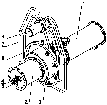
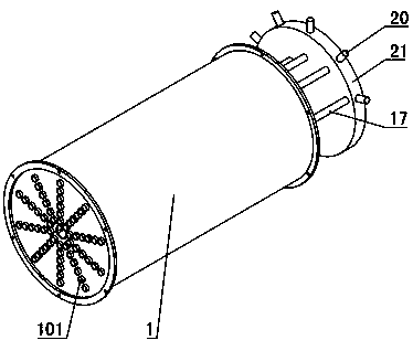
[0038] Such as Figure 1~5As shown: the heat exchanger 1 is a cylindrical shape with both ends closed, the heat exchanger 1 is arranged horizontally, and a plurality of heat exchange tubes 101 are arranged at intervals in the heat exchanger 1, and both ends of the heat exchange tubes 101 extend out for heat exchange At the corresponding end of the heat exchanger 1, the heat exchange tube 101 is arranged parallel to the axis of the heat exchanger 1, and a plurality of fins are arranged at intervals along the axial direction in the heat exchanger 1, and the fins are semicircular, and the heat exchange tube 101 passes through The fins are fixedly connected to the heat exchanger 1, which not only facilitates the installation of the heat exchange tube 101, but also increases the heat exchange area and improves the heat exchange efficiency. Both ends of the heat exchanger 1 are coaxially provided with flanges.

[0039] A water inlet tube is coaxially installed on the left end of th...

Embodiment 2

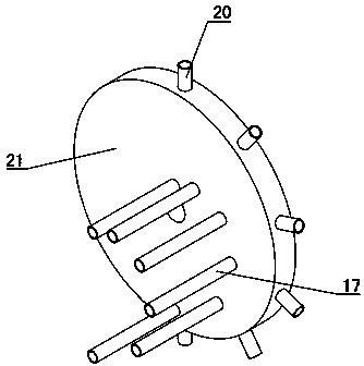
[0048] Such as Figure 7 As shown, the difference between Embodiment 2 and Embodiment 1 is that: one end of the water inlet cylinder is provided with a flushing bin 16 and a pushing mechanism, there are multiple flushing bins 16 spliced ​​into a ring coaxial with the heat exchanger 1, and each flushing bin 16 A plurality of flushing pipes 17 are arranged on the side close to the heat exchanger 1, and the flushing pipes 17 correspond to the heat exchange tubes 101 one by one and are arranged coaxially with the corresponding heat exchange pipes 101. The mechanism is connected with the flushing chamber 16 one by one and pushes it to translate, so that the flushing pipe 17 on the flushing chamber 16 communicates with the water inlet end of the corresponding heat exchange tube 101; the pushing mechanism includes a feed motor 4, a conversion motor 5, a shift fork 19 and Screw 11, the screw 11 is coaxially arranged with the heat exchanger 1, the shift fork 19 is provided with a nut 1...


PUM


Abstract

The invention relates to a heat exchanger with a washing function and belongs to the technical field of cleaning for heat exchangers. The heat exchanger is characterized in that multiple columns of heat exchange pipes (101) are arranged in the radius direction of a heat exchanger body (1), each column contains the same number of heat exchange pipes (101), and the number of washing pipes (17) of adistribution disc (21) is equal to that of the heat exchange pipes (101) contained in each column; the distance between each washing pipe (17) and the center of the distribution disc (21) is equal tothat between the heat exchange pipe (101) corresponding to each washing pipe (17) and the center of the heat exchanger body (1), water inlets (20) corresponding to the washing pipes (17) one to one are formed in the side of the distribution disc (21), and a pushing mechanism is connected with the distribution disc (21) and drives the distribution disc (21) to move. According to the heat exchangerwith the washing function, online cleaning for the heat exchanger body is achieved, convenience is provided for cleaning, cleaning is complete, the heat exchange efficiency of the heat exchanger is guaranteed, and application of the heat exchanger cannot be hindered when the heat exchange pipes are cleaned.

Description

technical field [0001] A heat exchanger with a flushing function belongs to the technical field of heat exchanger cleaning. Background technique [0002] The shell-and-tube heat exchanger, also known as the shell-and-tube heat exchanger, is a wall-type heat exchanger that uses the wall of the tube bundle enclosed in the shell as the heat transfer surface. This heat exchanger has a simple structure, reliable operation, and can be used in various Made of structural materials (mainly metal materials), it can be used under high temperature and high pressure, and is currently the most widely used type. [0003] Oil fields usually use shell-and-tube heat exchangers to recover geothermal energy in oil fields, so as to use geothermal heat to increase oil temperature, reduce oil viscosity, and facilitate oil transportation. Because the water in the oil field contains too much oil and impurities, when using There will be scale in the heat exchange tube of the shell and tube heat exch...

Claims


Application Information

Patent Timeline
Patent Type & Authority Applications(China)
IPC IPC(8): F28D7/16F28G9/00
CPCF28D7/16F28G9/00
Inventor 马立修孙贤明申晋巩秀钢陈文钢孙霞王聪孙冬刘冲
Owner SHANDONG UNIV OF TECH
Why Eureka
Try Eureka