Novel GNSS receiver incline measuring system and method

A technology of tilt measurement and receiver, which is applied in the field of high-precision tilt measurement system of GNSS receiver, can solve the problems of not dare to use, limited distribution of space points, cumbersome calibration, etc., to improve work efficiency, continuous high-precision tilt measurement, The effect of reducing labor intensity

Active Publication Date: 2019-01-25
SHANGHAI HUACE NAVIGATION TECH
View PDF3 Cites 27 Cited by
  • Summary
  • Abstract
  • Description
  • Claims
  • Application Information

AI Technical Summary

Problems solved by technology

[0006] Since the accelerometer cannot distinguish motion acceleration and gravitational acceleration, the electronic compass tilt measurement technology can only perform tilt measurement under quasi-static conditions. Even if the gyroscope is added to increase the dynamics of angle tracking, due to the existence of IMU system errors and random errors, Still unable to achieve real-time tilt measurement;
[0007] The magnetometer needs to be calibrated before each use. The correction effect directly affects the accuracy of the heading angle measurement, and the magnetometer is easily affected by the change of the electromagnetic environment inside and outside the receiver during use, and the change is difficult to monitor. Therefore, the magnetometer measures The reliability of the value is poor;
[0008] Due to the shortcomings of the tilt measurement scheme based on the electronic compass, such as absolute accuracy cannot be guaranteed, cumbersome calibration, and poor reliability, surveyors are unwilling or afraid to use it in practical applications.
[0009] The current method based on the second type of scheme is mainly the "shaking" tilt measurement method. This method measures multiple points in the space by shaking the centering rod, and uses the length of the centering rod as a constraint to carry out spatial intersection to calculate the position of the measurement point. However, due to the influence of the geometric structure of the distribution of spatial points, especially in environments such as wall corners, the distribution of spatial points is limited and the geometric structure is poor, so the accuracy of the measurement points is not stable, and can only achieve decimeter-level accuracy, and it is necessary to measure multiple Space point to complete tilt measurement

Method used


Image

  • Novel GNSS receiver incline measuring system and method
  • Novel GNSS receiver incline measuring system and method
  • Novel GNSS receiver incline measuring system and method

Examples


specific Embodiment approach

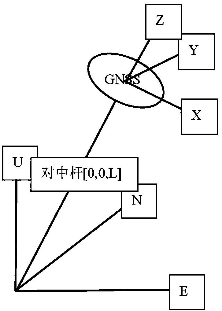
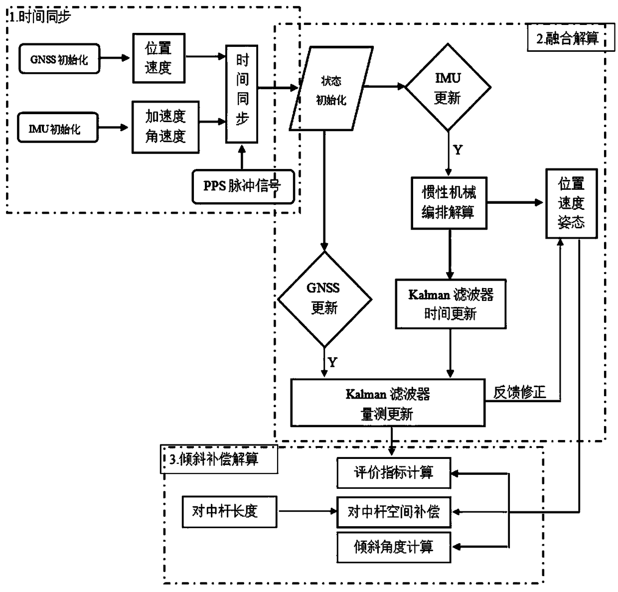
[0055] refer to Figure 3b As shown, GNSS receiver 1 includes an antenna for receiving satellite electromagnetic wave signals and a board card for GNSS navigation and positioning calculation, which is used to realize GNSS navigation and positioning calculation, output GNSS original observation data, PPS second pulse signal and antenna phase center velocity and position information; the IMU inertial measurement module 2 installed at the center of the GNSS receiver is used to measure the linear velocity and angular velocity in three orthogonal directions of the IMU for inertial mechanical arrangement and calculation; the CPU processor 3 mainly realizes GNSS navigation Positioning information, time synchronization of IMU inertial observation data, IMU inertial mechanical arrangement and calculation, GNSS / INS data fusion calculation and space vector tilt compensation and other algorithms operation; centering pole 4, GNSS antenna phase center position and measurement point The phys...


PUM


Abstract

The invention provides a novel GNSS receiver incline measuring system. The system comprises an inertia measuring unit, a GNSS receiver, a CPU and a centering rod, wherein the inertia measuring unit comprises a three-axis accelerometer and a three-axis gyroscope, the GNSS receiver is used for measuring the position and velocity of an antenna phase position center of the receiver, the CPU is used for data processing and responsible for the synchronization of GNSS receiver data and inertia measuring unit data, and the centering rod is a physical medium of the position transmission of the GNSS receiver and a measuring point. By means of the system, reliable, consecutive and high-precision incline measuring without correction is achieved to take the place of an incline measuring method based onan electronic compass technology and a 'shaking' technology, the working efficiency of field measurement of the GNSS receiver is improved, and the working intensity of a measuring worker is reduced.

Description

technical field [0001] The invention belongs to a scheme design and implementation method of a high-precision tilt measurement system for a GNSS receiver, and is suitable for various measurement fields such as surveying and mapping, engineering surveying, and monitoring by using a GNSS receiver and a centering pole to perform point measurement and stakeout. Background technique [0002] The GNSS receiver measures the coordinate position of the antenna phase center, but what is needed in practical applications is the coordinate position of the corresponding point at the bottom of the centering pole. The traditional operation method needs to keep the level bubble on the centering pole in the center, and set the antenna phase center position It is transmitted to the corresponding measurement point at the bottom of the measuring rod, which has low operating efficiency and high labor intensity, and the environment such as wall corners and slopes does not have the objective conditi...

Claims


Application Information

Patent Timeline
Patent Type & Authority Applications(China)
IPC IPC(8): G01C9/00G01C21/16G01S19/47
CPCG01C9/00G01C21/165G01S19/47
Inventor 邓海峰袁本银沈雪峰谢惠颖梁越李早玲徐恩强
Owner SHANGHAI HUACE NAVIGATION TECH
Why Eureka
Try Eureka