
Efficient automatic core aligning device for fiber fusion splicer

An optical fiber fusion splicer, high-efficiency technology, applied in the direction of light guide, optics, optical components, etc., can solve the problems of motion accuracy restriction, difficult to keep up, etc., to achieve the effect of improving the quality of optical fiber fusion, fast adjustment speed, and compact structure

Active Publication Date: 2019-01-25
南京迪威普光电技术股份有限公司
View PDF6 Cites 3 Cited by
  • Summary
  • Abstract
  • Description
  • Claims
  • Application Information

AI Technical Summary

Problems solved by technology

[0003] The design concept of the core alignment device is to form an effective precision drive in a limited space to align the end faces of the optical fibers on the two core alignment frames on the same axis, such as the three-dimensional automatic alignment core alignment device of the optical fiber fusion splicer disclosed in CN201373927Y. The cross-alignment method uses the cam and the slider to drive the two aligning frames to move in the cross direction respectively. However, the movement accuracy of the device is restricted by the cam shape and the processing capacity of the guide groove, and it is difficult to keep up with the increasing Increased alignment accuracy is required when

Method used


Image

  • Efficient automatic core aligning device for fiber fusion splicer
  • Efficient automatic core aligning device for fiber fusion splicer
  • Efficient automatic core aligning device for fiber fusion splicer

Examples


Embodiment

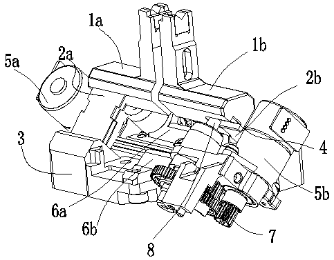
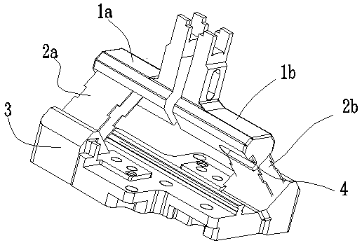
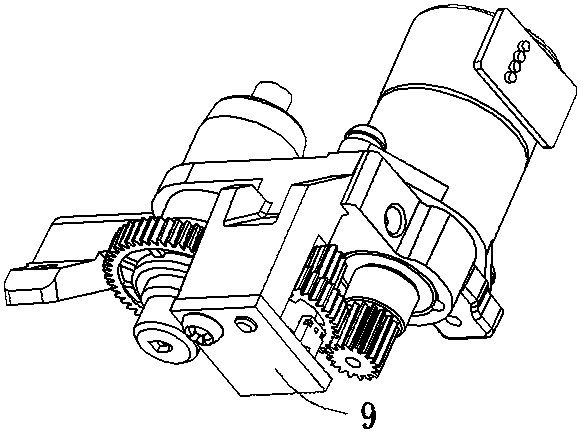
[0023] The high-efficiency automatic core alignment device of the optical fiber fusion splicer in this embodiment is as follows: figure 1 As shown, including aligning frame assembly and power assembly. The centering frame assembly is formed by the left and right centering frames 1a and 1b, which are fixedly connected to the centering frame base 3 via two left and right elastic supporting pieces 2a and 2b. The power assembly is installed on the centering frame assembly through screws, and its layout is also a pair of central symmetry, including the left motor 5a and the left connecting frame 6a, and the right motor 5b and the right connecting frame 6b, both of which are equipped with a gear mechanism 7 and a wire The rod mechanism 8 and the lead screw mechanism 8 are used to lift the centering frame. Since the centering frame and the base of the centering frame are connected by an elastic support piece, the elastic support piece is installed obliquely at 45°, and the output rot...


PUM


Abstract

The invention provides an efficient automatic core aligning device for a fiber fusion splicer. The efficient automatic core aligning device comprises a core adjusting frame assembly and a power assembly. The integrated core adjusting frame assembly is formed by connecting a base with left and right core adjusting frames by means of left and right elastic supporting pieces, the left and right elastic supporting pieces are distributed in central symmetry, and planes on which the left and right elastic supporting pieces locate form a 90-degree included angle; portions, embedded in the core adjusting frames, of the elastic supporting pieces serve as fulcrums; the power assembly has a connecting plate; a motor, a gear mechanism and a lead screw mechanism are mounted on the connecting plate, thelead screw mechanism is used for pushing the fulcrums, the gear mechanism is composed of a motor output gear, an intermediate gear and lead screw driving teeth which are sequentially engaged, tile-shaped protrusions are arranged on the end surface of the intermediate gear, and the connecting plate is further provided with a slot type photoelectric sensor for identifying the tile-shaped protrusions. The efficient automatic core aligning device realizes the miniaturization and light-weight trend of the whole fiber fusion splicer, has compact double core alignment structures and fast adjustmentspeed, improves the precision and stability of core alignment, and improves the optical fiber fusion quality.

Description

technical field [0001] The invention relates to a device for connecting optical fibers through fusion, in particular to a high-efficiency automatic core alignment device for an optical fiber fusion splicing machine. Background technique [0002] The quality of optical fiber fusion is generally judged by the fusion loss and the strength of the fusion point. Among them, the size of the splice loss is more critical. Improving and improving the fiber-to-core level is the main way to reduce splicing loss and improve splicing quality. During fiber splicing, the alignment of the fiber core is very important, and the alignment accuracy of the alignment device directly affects the alignment level. [0003] The design concept of the core alignment device is to form an effective precision drive in a limited space to align the end faces of the optical fibers on the two core alignment frames on the same axis, such as the three-dimensional automatic alignment core alignment device of th...

Claims


Application Information

Patent Timeline
IPC IPC(8): G02B6/255
CPCG02B6/2555G02B6/2557
Inventor 潘泳
Owner 南京迪威普光电技术股份有限公司
Learn More