
Practical liquid crystal display module

A liquid crystal display module and liquid crystal display panel technology, applied in the direction of nonlinear optics, instruments, optics, etc., can solve the problems of thermal expansion of the light guide plate, affecting the normal operation of the light bar, affecting the use effect and life of the liquid crystal display module, etc. Reach the requirements of reducing thermal conductivity, increase the range of selection, and improve the effect of heat dissipation

Pending Publication Date: 2019-01-25
BENGBU GUOXIAN TECH CO LTD
View PDF0 Cites 0 Cited by
  • Summary
  • Abstract
  • Description
  • Claims
  • Application Information

AI Technical Summary

Problems solved by technology

[0002] The liquid crystal display module has many advantages such as thin body and power saving, and is widely used in devices such as handheld computers, computer screens, and notebook screens. In the prior art, the LED light bar is placed inside the back panel, and the LED light The heat of the strip is dissipated, and the outer frame and the plastic frame are fixed to fix the LCD panel. When the LED light strip is working, a lot of heat will be generated. The heat is concentrated on the inner side of the back panel and it is difficult to dissipate effectively. Continuous high temperature will not only affect the light strip. Normal operation will easily cause the light guide plate to expand due to heat, which will seriously affect the overall use effect and life of the liquid crystal display module

Method used


Image

  • Practical liquid crystal display module
  • Practical liquid crystal display module

Examples


Embodiment Construction

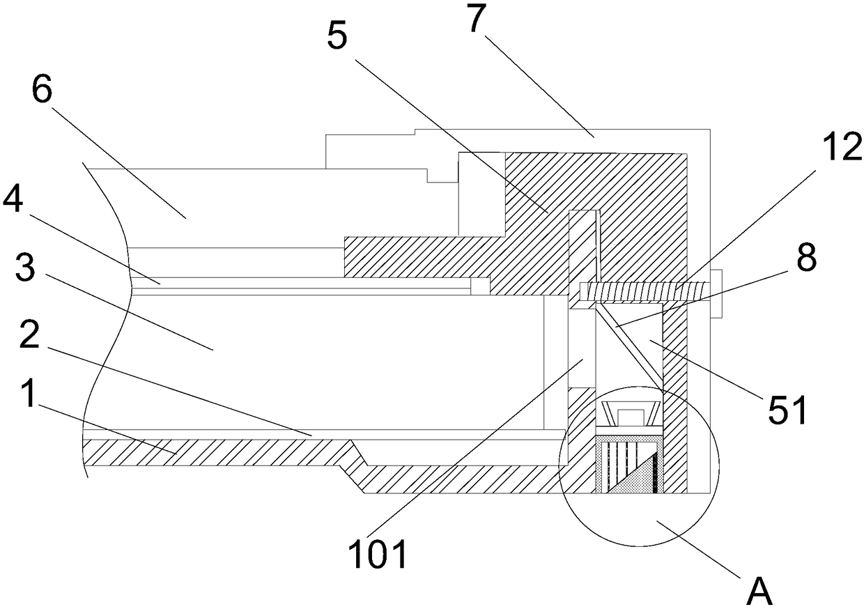
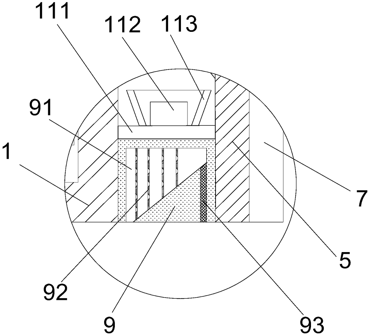
[0016] refer to figure 1 with figure 2 As shown, a practical liquid crystal display module proposed by the present invention includes a back plate 1, a reflective sheet 2, a light guide plate 3, an optical film material 4, a plastic frame 5, a liquid crystal display panel 6, an outer frame 7, and a reflective mirror 8 , cooling block 9 and LED light bar;

[0017] The reflective sheet 2 is installed on the backplane 1, the light guide plate 3 is installed on the top of the reflective sheet 2, the optical film material 4 is installed on the top of the light guide plate 3, the plastic frame 5 is set on the backplane 1, and the liquid crystal display panel 6 is installed on the plastic frame 5, and located above the optical film material 4, the outer frame 7 is sleeved on the plastic frame 5, a light guide through hole 101 is provided on the side of the back plate 1 corresponding to the position of the light guide plate 3, and the plastic frame 5 is located on the back plate An...


PUM


Abstract

The invention discloses a practical liquid crystal display module, which comprises a back plate, a reflector, a light guide plate, an optical film, a plastic frame, a liquid crystal display panel, anouter frame, a reflecting mirror, a heat radiating block and an LED light strip. The reflector is mounted on the back plate, the light guide plate is mounted above the reflector, the optical film is mounted above the light guide plate, the plastic frame sleeves the back plate, the liquid display panel is mounted in the plastic frame and positioned above the optical film, and the outer frame sleeves the plastic frame. The lateral side of the back plate is provided with a light guide through hole corresponding to the light guide plate, the plastic frame is provided with a mounting groove at theposition of the lateral side of the back plate, and the light guide through hole is communicated with the mounting groove. A position, corresponding to the light guide through hole, of the reflectingmirror is obliquely mounted in the mounting groove, the heat radiating block is mounted in the mounting groove and positioned below the reflecting mirror, the LED light strip is mounted above the heatradiating block, and the lower portion of the heat radiating block is provided with a heat radiating groove. The practical liquid crystal display module is simple in structure and convenient to use,and integral heat radiating effects of the liquid crystal display module are remarkably improved.

Description

technical field [0001] The invention relates to the technical field of liquid crystal display, in particular to a practical liquid crystal display module. Background technique [0002] The liquid crystal display module has many advantages such as thin body and power saving, and is widely used in devices such as handheld computers, computer screens, and notebook screens. In the prior art, the LED light bar is placed inside the backplane, and the LED light The heat of the strip is dissipated, and the outer frame and the plastic frame cooperate to fix the LCD panel. When the LED light strip is working, a lot of heat will be generated. The heat is concentrated on the inner side of the back panel and it is difficult to dissipate effectively. Continuous high temperature will not only affect the light strip. Normal operation will easily cause the light guide plate to expand due to heat, which will seriously affect the overall use effect and lifespan of the liquid crystal display mo...

Claims


Application Information

Patent Timeline
Patent Type & Authority Applications(China)
IPC IPC(8): G02F1/1333G02F1/13357
CPCG02F1/133385G02F1/133615G02F1/133628
Inventor 欧木兰朱了了朱颂
Owner BENGBU GUOXIAN TECH CO LTD
Learn More