Centering supporting mechanism, car coupler buffering device adopting centering supporting mechanism and centering method

A technology of support mechanism and buffer device, which is applied in the field of coupler buffer device and centering support mechanism, can solve the problems of inconvenient regulation and complex structure, and achieve the effect of automatic vehicle coupling and roller force dislocation

Pending Publication Date: 2019-01-29
QINGDAO SRI TECH CO LTD
View PDF1 Cites 8 Cited by
  • Summary
  • Abstract
  • Description
  • Claims
  • Application Information

AI Technical Summary

Problems solved by technology

However, its structure is complex and inconvenient to regulate

Method used


Image

  • Centering supporting mechanism, car coupler buffering device adopting centering supporting mechanism and centering method
  • Centering supporting mechanism, car coupler buffering device adopting centering supporting mechanism and centering method
  • Centering supporting mechanism, car coupler buffering device adopting centering supporting mechanism and centering method

Examples


Embodiment 1

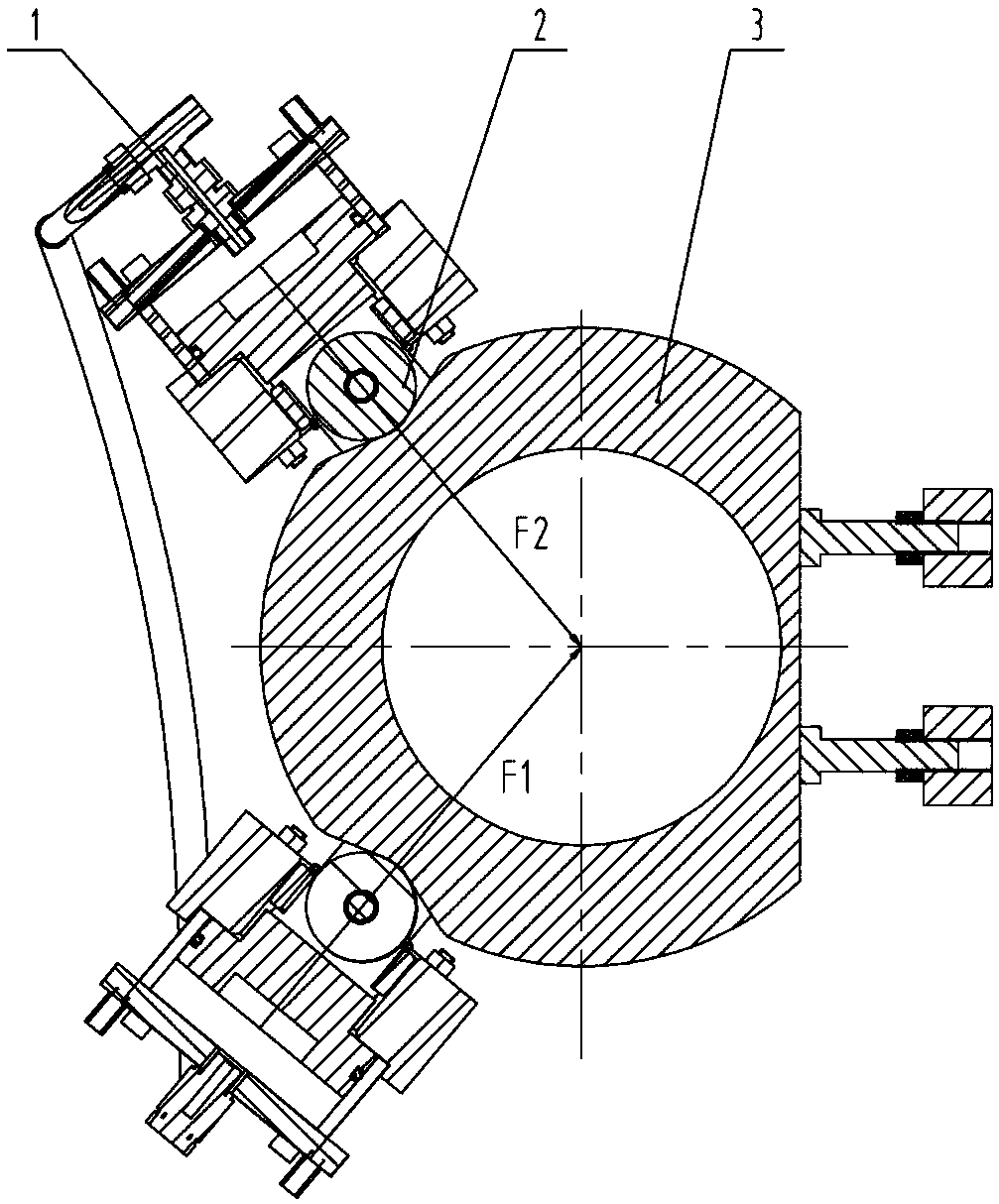
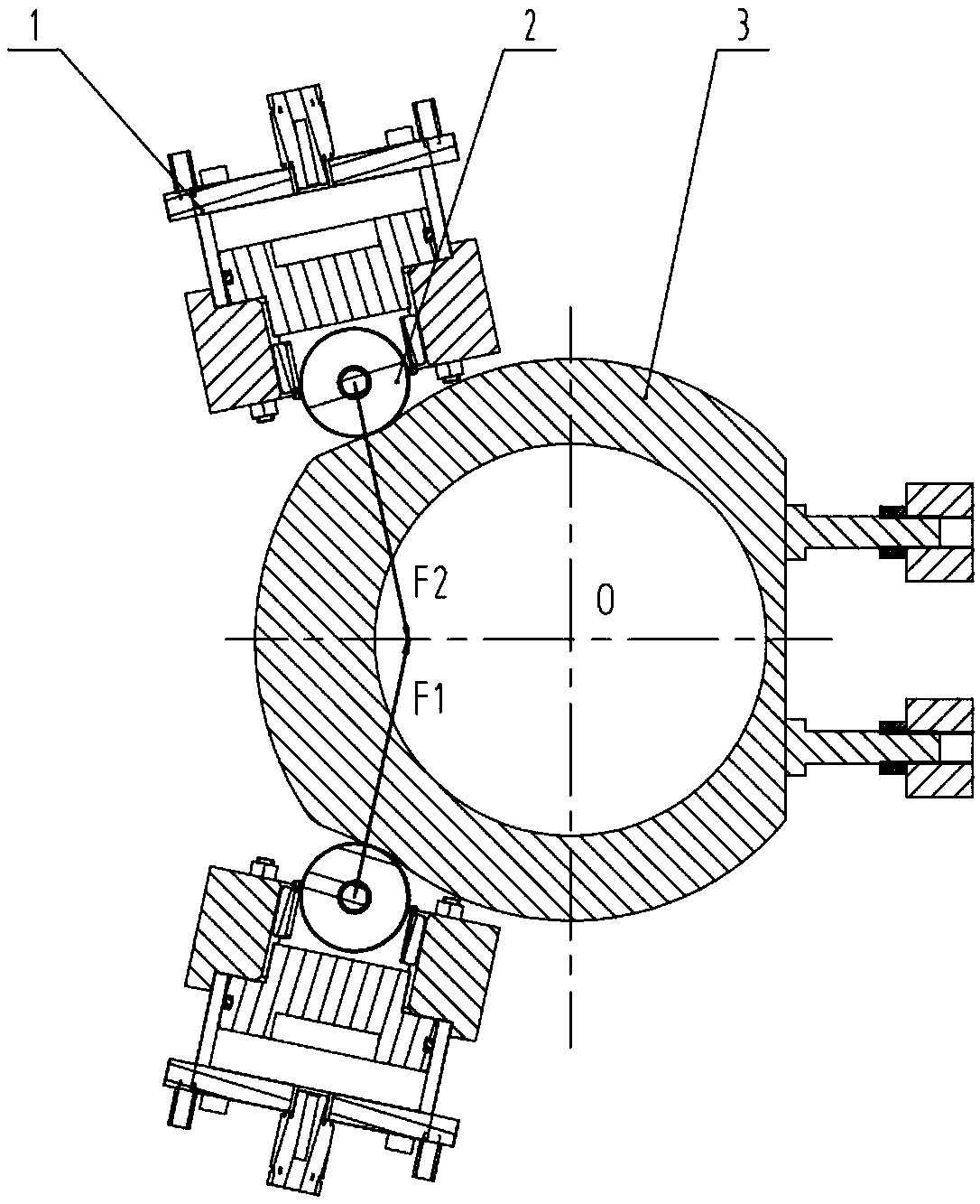
[0031] The basic structure of the centering support mechanism of this embodiment is as follows: figure 2 shown (see image 3 , Figure 4 ), the hinged hole in the center of the center plate 3 forms the coupler swing center O, and the two sides of the coupler extension direction (horizontal direction through the swing center in the figure) are symmetrically placed on both sides of the pneumatic pressure device 1, and the piston of the pneumatic pressure device 1 The cam pair is formed by the circular arc recess of the roller 2 and the centering disc 3 .

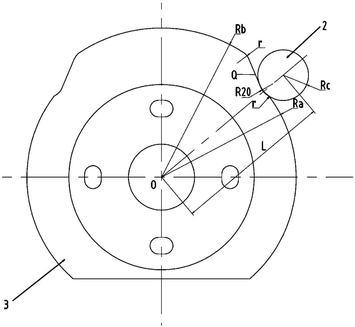
[0032] Such as image 3 As shown, the outer profile of the centering plate 3 has a large-diameter section corresponding to the space between the two pneumatic pressure-applying devices 1 with a radius of Rb, and a small-diameter section corresponding to the outside of the two pneumatic pressure-applying devices 1 with a radius of Ra and a radius of R20 The circular arc depression of the centering disc 3 is adjacent to the ...

Embodiment 2

[0041] The technical solution of this embodiment is basically the same as that of Embodiment 1, the difference lies in that the outline curve of the middle plate 3 is optimized.

[0042] The outline of the centering plate 3 of the centering support mechanism is constituted as follows: Figure 7 As shown, as in Embodiment 1, there is a large-diameter section corresponding to two pneumatic pressure-applying devices 1 with a radius of Rb and a small-diameter section corresponding to the outside of the two pneumatic pressure-applying devices 1 with a radius of Ra, and a radius of R20 The arc sag, the optimization point is that the tangent between the arc sag and the large-diameter section of the centering plate 3 is the diameter-increasing arc Q' of the radius RQ (2000mm in this embodiment), and its center is in the centering The position is on the line of the force direction of the pressing device passing the center of the roller circle. In this way, it is easier to perceive the...


PUM


Abstract

The invention relates to a centering supporting mechanism, a car coupler buffering device adopting the centering supporting mechanism and a centering method, and belongs to the technical field of moving vehicles. The centering supporting mechanism comprises a centering disc forming the car coupler swing center, and pressuring devices located on two sides of the extending direction of a car coupler. The pressuring devices form cam pairs with centering grooves of the centering disc by idler wheels. The centering grooves are close to the small diameter section of the centering disc, and are connected with the large diameter section of the centering disc by a diameter-increasing curve. The pressuring directions of the pressuring devices departure the swinging center of the centering disc towards the large diameter section by idler wheel centers falling into the centering grooves. The problems of automatic coupling of vehicles on a curved track and roller force dislocation are cleverly solved by simple and reasonable design for the centering disc profile combined with pressure bias.

Description

technical field [0001] The invention relates to a centering support mechanism, a coupler buffer device using the mechanism, and a corresponding centering method, belonging to the technical field of walking vehicles. Background technique [0002] The coupler buffer device plays the role of connecting the vehicle and mitigating the impact, and is a key component in the rail vehicle. The centering support mechanism fixes the coupler on the longitudinal axis of the vehicle in the horizontal direction through rubber, spring or other elastic elements, and makes the overall vertical height of the coupler consistent in the vertical direction, so that the phenomenon of "head up and down" does not occur. , to facilitate the coupler to hang. The centering support mechanism can also realize the automatic centering function within a certain angle. [0003] The existing centering support mechanism closest to the application such as figure 1 shown (see Figure 6 ), including the center...

Claims


Application Information

Patent Timeline
Patent Type & Authority Applications(China)
IPC IPC(8): B61G7/06
CPCB61G7/06
Inventor 殷杰吴刚季天莹张琳
Owner QINGDAO SRI TECH CO LTD
Why Eureka
Try Eureka