Prefabrication combined box type underground diaphragm wall and construction method thereof

An underground diaphragm wall and construction method technology, applied in sheet pile walls, foundation structure engineering, construction, etc., can solve the problems of pre-embedded steel bars on floors, inaccurate positioning of connectors, high civilized construction costs, and difficult construction. Achieve the effects of improving civilized construction standards and intelligence, reducing building sheds and material stacking, reducing noise and environmental management costs

Pending Publication Date: 2019-01-29
GUANGZHOU METRO DESIGN & RES INST
View PDF0 Cites 5 Cited by
  • Summary
  • Abstract
  • Description
  • Claims
  • Application Information

AI Technical Summary

Problems solved by technology

[0004] (1) Manual tying and welding of reinforcement cages is difficult to control and standardize the production quality, the construction site is large, and the cost of civilized construction is high; (2) The collapse of the groove wall will make it difficult to sink and place the reinforcement cages in the underground diaphragm wall, making it difficult to place and floating , affecting safety; (3) Underwater concrete pouring has local arching and boundary invasion due to collapse holes, increasing the risk of manual processing; (4) The joints of the underground diaphragm wall are made of I-beams or pipes, and the concrete pouring is not dense, resulting in joints Water leakage and sand leakage and other subsidence risks; (5) The concrete pouring of the underground diaphragm wall should not be compacted or layered and segregated, which will affect risks such

Method used


Image

  • Prefabrication combined box type underground diaphragm wall and construction method thereof
  • Prefabrication combined box type underground diaphragm wall and construction method thereof
  • Prefabrication combined box type underground diaphragm wall and construction method thereof

Examples


Example Embodiment

[0051] The preferred embodiments of the present invention will be described below in conjunction with the accompanying drawings. It should be understood that the preferred embodiments described here are only used to illustrate and explain the present invention, and are not intended to limit the present invention.

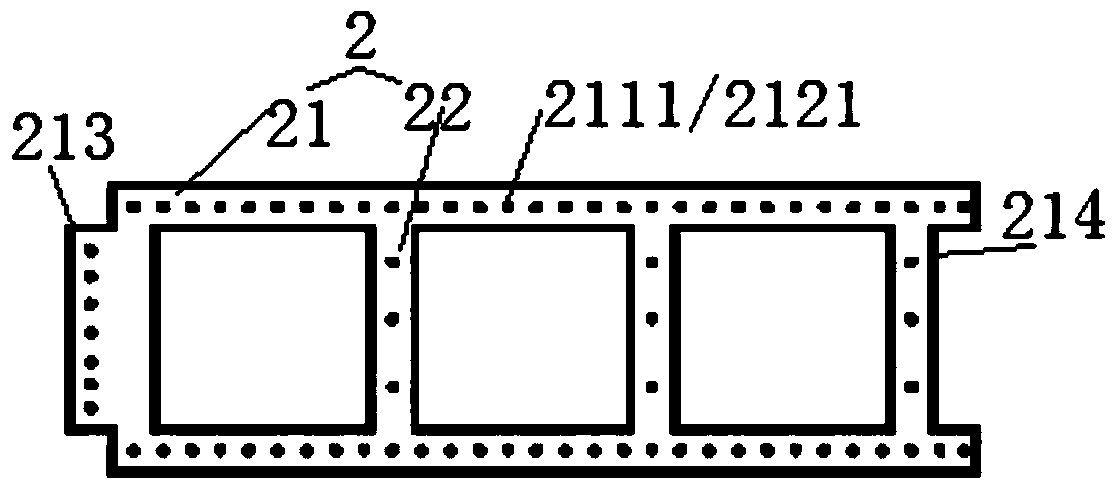
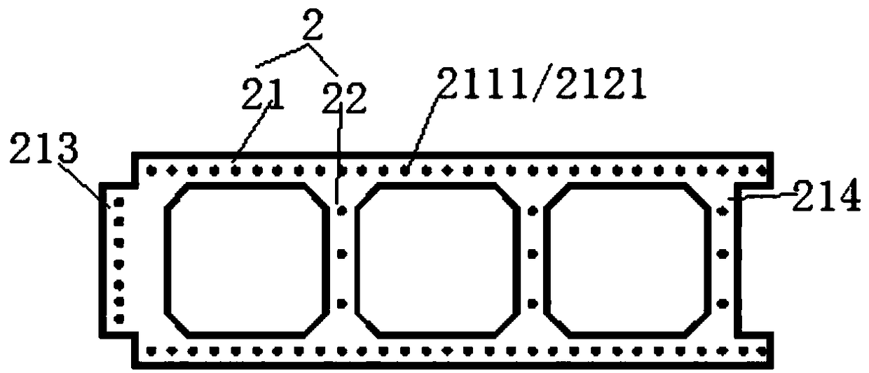
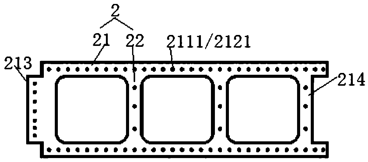
[0052] The invention discloses a prefabricated combined box type underground continuous wall, such as Figure 1-18 As shown, it includes a prefabricated box-type underground diaphragm wall component 2 as a retaining structure for the foundation pit. The prefabricated box-type underground diaphragm wall component 2 includes a box body 21 with a hollow portion 215 and a web 22 arranged in the box body 21. ;

[0053] The vertical ends of the box 21 are provided with a first tenon 211 or a first mortise 212; the lateral ends of the box 2 are provided with a second tenon 213 or a second mortise 214; adjacent prefabricated box-type underground continuous wall components ...


PUM

PropertyMeasurementUnit
Widthaaaaaaaaaa
Thicknessaaaaaaaaaa

Abstract

The invention discloses a prefabrication combined box type underground diaphragm wall comprising prefabrication box type underground diaphragm wall components as foundation pit retaining structures. Each prefabrication box type underground diaphragm wall component comprises a box provided with a hollow part, and a web arranged in the box, wherein the vertical two ends of the box are provided withfirst tenons or first mortises, and the transverse two ends of the box are provided with second tenons or second mortises. Adjacent prefabrication box type underground diaphragm wall components are connected through mortise-tenon structures to form a combined box type underground diaphragm wall body. The invention further discloses a construction method of the prefabrication combined box type underground diaphragm wall. For the prefabrication combined box type underground diaphragm wall and the construction method thereof, the box type underground diaphragm wall components made through factory-like concentrated prefabrication are adopted for plane and vertical combined assembly of a foundation pit, any foundation pit plane forms can be formed, flexibility is achieved, prefabrication quality is high, constriction quality is stable, stress participation can be conducted in time, a large amount of labor force is saved, and cost is reduced.

Description

technical field [0001] The invention belongs to the technical field of underground diaphragm wall structures, and in particular relates to a prefabricated combined box-type underground diaphragm wall and a construction method thereof. Background technique [0002] The construction process of the underground diaphragm wall is to use a special groove forming machine to excavate under the condition of mud retaining wall to form a groove of a certain length, then put the steel cage processed on the ground into the groove section, and sink it to a certain depth After fixing, the conduit is used for underwater concrete pouring to complete a unit wall section, and then the subsequent wall sections are constructed sequentially. The wall sections are connected to each other by specific joints to form a continuous reinforced concrete wall, which can be used as a water cutoff , anti-seepage, load-bearing, water-retaining structure. [0003] The construction process of the existing und...

Claims


Application Information

Patent Timeline
IPC IPC(8): E02D5/10E02D5/12
CPCE02D5/10E02D5/12E02D2300/002
Inventor 杨德春裴行凯王志红唐琪杨璐菡王世君刘金燕
Owner GUANGZHOU METRO DESIGN & RES INST
Why Eureka
Try Eureka