Electrically-driven gear transmission plunger pump

A gear transmission and plunger pump technology, applied in the field of plunger pumps, can solve the problems of long development and selection cycle, high process requirements, and many interconnected links, shortening the selection and product development process, and expanding the scope of application. , compact structure

Pending Publication Date: 2019-01-29
温州市基安机械有限公司 +1
View PDF0 Cites 1 Cited by
  • Summary
  • Abstract
  • Description
  • Claims
  • Application Information

AI Technical Summary

Problems solved by technology

[0002] Most of the plunger pump power drives on the market today are the assembly combination of motor, reducer and plunger pump body. To reasonably match and select the components, it requires high technology and many interconnection links. And the process requirements are high, and the development and selection cycle is long

Method used


Image

  • Electrically-driven gear transmission plunger pump
  • Electrically-driven gear transmission plunger pump
  • Electrically-driven gear transmission plunger pump

Examples


Embodiment Construction

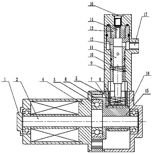
[0029] The present invention will be further described in detail below with reference to the accompanying drawings.

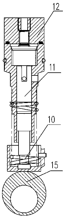
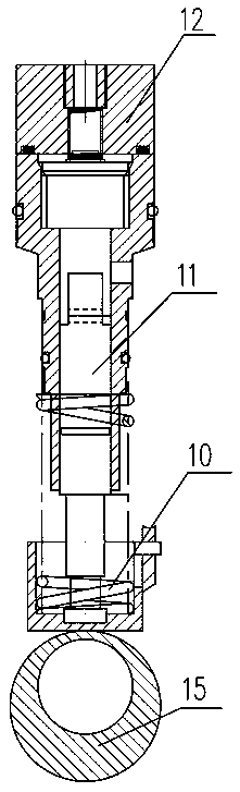
[0030] For specific implementation: see Figure 1 to Figure 4 , An electrically driven gear transmission plunger pump, comprising a motor 1, a reduction transmission mechanism with a small tooth difference and a plunger pump body. The input end of the reduction transmission mechanism with a small tooth difference is connected to the output shaft 2 of the motor 1, and The output end of the tooth difference reduction transmission mechanism rotates eccentrically and is connected with the plunger pump core 11 in the plunger pump body to drive the plunger pump core 11 to move up and down linearly in the plunger pump body.

[0031] In this way, the motor, the reduction mechanism and the plunger pump body are combined to complete the integration of electromechanical and hydraulic integration, complementary advantages and disadvantages, ingenious combination of structures, ...


PUM


Abstract

The invention discloses an electrically-driven gear transmission plunger pump. The electrically-driven gear transmission plunger pump comprises a motor, a small-tooth-difference speed reducing transmission mechanism and a plunger pump body, the input end of the small-tooth-difference speed reducing transmission mechanism is connected with an output shaft of the motor, and the output end of the small-tooth-difference speed reducing transmission mechanism eccentrically rotates and is connected with a plunger pump core in the plunger pump body to drive the plunger pump core to do vertical reciprocating linear motion in the plunger pump body. Therefore, the motor, the speed reducing mechanism and the plunger pump body are combined to complete mechanical-electrical-hydraulic integration, advantages and disadvantages are complementary, the structures are skillfully combined, parts are reduced, the cost is reduced, the functions are integrated, application is convenient, and the application range field is greatly widened; the structure is compact, the size is small, and the position precision is high; and the small-tooth-difference speed reducing transmission mechanism skillfully drives the plunger pump core to do reciprocating motion, a tedious output mechanism is omitted, the industry model selection and product development process is greatly and professionally shortened, and the electrically-driven gear transmission plunger pump is especially suitable for vehicles, air vehicles, small robot fixtures and the like.

Description

Technical field [0001] The invention belongs to the field of plunger pumps, and particularly relates to an electrically driven gear drive plunger pump. Background technique [0002] Most of the plunger pump power drives on the market are the assembly combination of the three separate products of the motor, reducer and plunger pump body. To match and select the components reasonably, high technicality is required and there are many interconnected links. And the process requirements are high, and the development and selection cycle is long. Summary of the invention [0003] In view of the above-mentioned shortcomings of the prior art, the technical problem to be solved by the present invention is: how to provide an electric drive gear drive plunger pump, which highly integrates the motor, reducer and plunger pump body, realizes the triad plunger pump, develops and selects The model cycle is short, especially suitable for vehicles, aircrafts, small robot fixtures, etc. [0004] In or...

Claims


Application Information

Patent Timeline
IPC IPC(8): F04B17/03H02K7/075
CPCH02K7/075F04B17/03
Inventor 陈纪恩胡捷
Owner 温州市基安机械有限公司
Why Eureka
Try Eureka