Air cabinet with lifting function

A wind cabinet and functional technology, applied in the field of wind cabinets with lifting functions, can solve the problems of only fixed installation in a specific position, high installation and use costs of wind cabinets, and rising PM2.5 index, so as to reduce natural destruction and emission The wind effect is good and the effect of reducing external damage

Inactive Publication Date: 2019-01-29
合肥人和节能环保设备制造有限公司
View PDF6 Cites 1 Cited by
  • Summary
  • Abstract
  • Description
  • Claims
  • Application Information

AI Technical Summary

Problems solved by technology

The rapid development of the construction industry and modern industry has caused the rapid increase of harmful gases and dust in the air, resulting in the continuous rise of the PM2.5 index, causing persistent haze weather, which poses a serious threat to the healthy life of residents, and the impact of haze removal , Indoor environmental pollution caused by other factors is also becoming more and more serious, such as coal burning for heating, smoking, cooking fumes, and methanol volatilized from building materials, etc., especially in public places such as offices, bars, and Internet cafes, where there are many people, closed environments, and poor air quality. Circulation, and even cause symptoms such as human hypoxia. Because the air cabinet can exchange indoor and outdoor air and maintain the balance of indoor and outdoor air, it has gradually become an important part of interior design. However, most of the existing air cabinets are expensive to install and use. The effect is not good, and it can only be fixed and installed in a specific position, it is not universal, and it does not have the function of purifying the air

Method used


Image

  • Air cabinet with lifting function
  • Air cabinet with lifting function

Examples


Embodiment Construction

[0020] The following will clearly and completely describe the technical solutions in the embodiments of the present invention with reference to the accompanying drawings in the embodiments of the present invention. Obviously, the described embodiments are only some, not all, embodiments of the present invention. All other embodiments obtained by persons of ordinary skill in the art based on the embodiments of the present invention belong to the protection scope of the present invention.

[0021] According to an embodiment of the present invention, a wind cabinet with lifting function is provided.

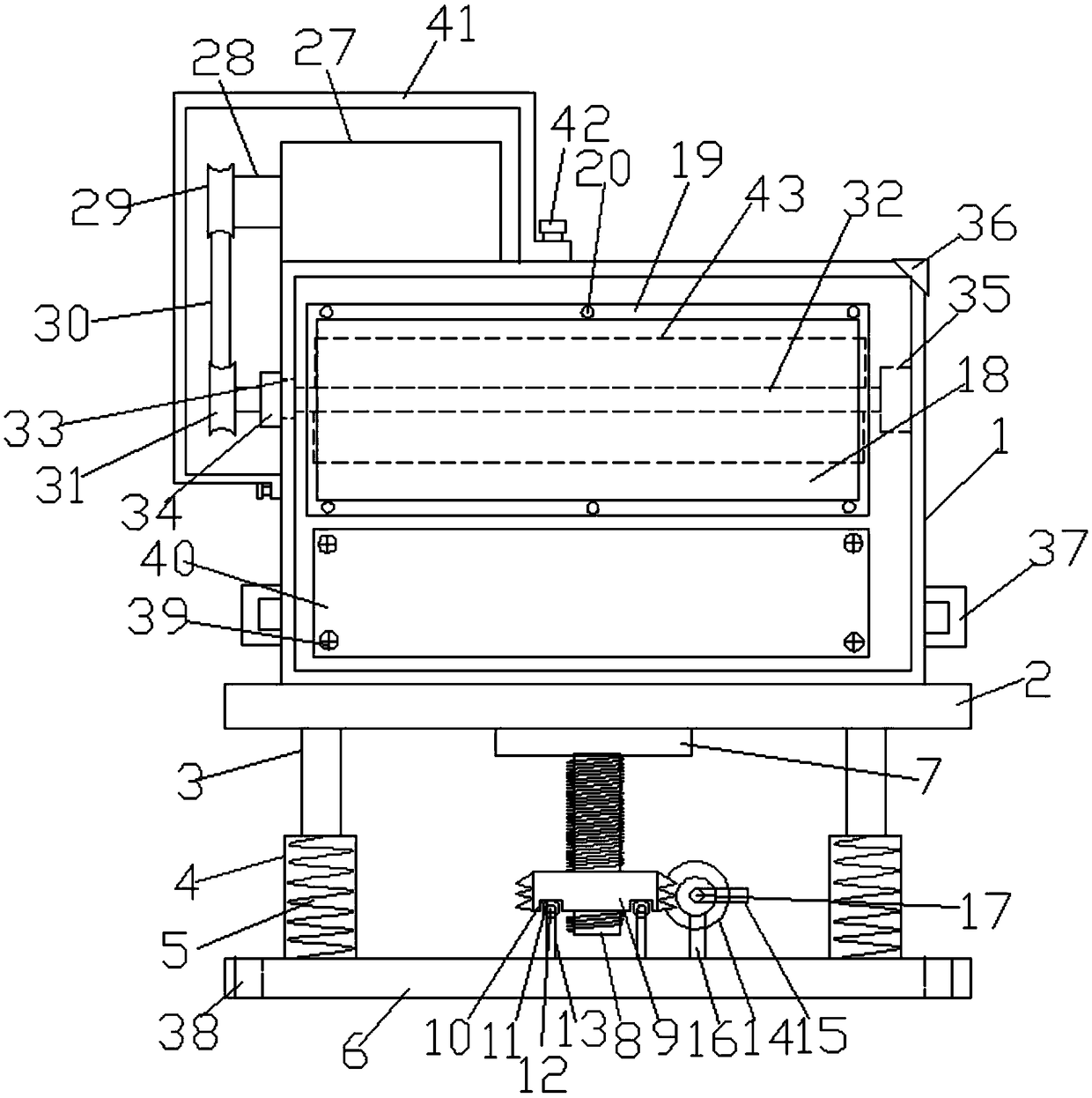
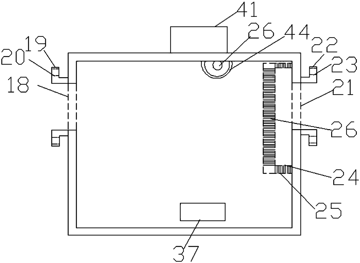
[0022] Such as Figure 1-2 As shown, a wind cabinet with a lifting function according to an embodiment of the present invention includes a wind cabinet 1, a support plate 2 is provided at the bottom end of the wind cabinet 1, and support rods are provided on both sides of the bottom end of the support plate 2 3. The bottom end of the support rod 3 is provided with a sleeve rod 4, a...


PUM


Abstract

The invention discloses an air cabinet with a lifting function. The air cabinet comprises an air cabinet body, wherein a supporting plate is arranged at the bottom end of the air cabinet body, supporting rods are both arranged on the two sides of the bottom end of the supporting plate, sleeve rods are arranged at the bottom ends of the supporting rods, springs are arranged in the sleeve rods, thetop ends of the springs are connected with the bottom ends of the supporting rods, a bottom plate is arranged at the bottom ends of the sleeve rods, a connecting plate is arranged at the middle part of the bottom end of the supporting plate, a screw rod is arranged at the middle part of the bottom end of the connecting plate, a gear I is arranged at the bottom end of the screw rod, the screw rod penetrates through the middle part of the gear I, sliding grooves are formed in the side edge of the bottom end of the gear I, a plurality of pulleys are arranged in the sliding grooves, connecting shafts I are arranged at the middle parts of the pulleys, supporting rods II are arranged on the connecting shafts I, the bottom ends of the supporting rods II are connected with the top end of the bottom plate, a gear II matched with the gear I is arranged on one side of the gear I, a connecting shaft II is arranged at the middle part of the gear II, a crank is arranged on the connecting shaft II, asupporting rod I is arranged in the bottom end of the gear II, the bottom end of the supporting rod I is connected with the top end of the bottom plate, and an air outlet is formed in one side of theair cabinet.

Description

technical field [0001] The invention relates to the technical field of wind cabinets, in particular to a wind cabinet with lifting function. Background technique [0002] With the deterioration of the global environment, nearly 17 million people die every year due to infection of various diseases, the most serious of which is respiratory tract infection. Living in turbid air for a long time will cause harm to the nervous system, respiratory system and immune system of the human body. , leading to decreased immunity and related diseases. The rapid development of the construction industry and modern industry has caused the rapid increase of harmful gases and dust in the air, resulting in the continuous rise of the PM2.5 index, causing persistent haze weather, which poses a serious threat to the healthy life of residents, and the impact of haze removal , Indoor environmental pollution caused by other factors is also becoming more and more serious, such as coal burning for heat...

Claims


Application Information

Patent Timeline
Patent Type & Authority Applications(China)
IPC IPC(8): F24F5/00F24F3/16F24F13/28F24F13/32
CPCF24F5/0096F24F13/28F24F13/32F24F8/10F24F8/167
Inventor 方涛
Owner 合肥人和节能环保设备制造有限公司
Why Eureka
Try Eureka