Hot-blast stove used for grain drying

A technology of hot blast stove and blast stove, which is applied in drying, drying machine, grain drying, etc. It can solve the problems of difficult cleaning, poor heat exchange temperature capability, and insufficient combustion of fuel, so as to facilitate inspection and repair work, The effect of stable hot air temperature and accelerated drying speed

Inactive Publication Date: 2019-01-29
周如彬
View PDF0 Cites 1 Cited by
  • Summary
  • Abstract
  • Description
  • Claims
  • Application Information

AI Technical Summary

Problems solved by technology

[0002] The so-called hot blast stove, of course, refers to the use of direct combustion of fuel, high purification treatment to form hot air, and direct contact with materials to heat, dry or bake. This method reduces fuel consumption by about half compared to steam or other indirect heaters. , without affecting the quality of drying products, it is completely possible to use direct high-purification hot air. Through long-term production practice, people have realized that only by using hot air as a medium and carrier can the heat utilization rate and thermal work be greatly improved. As a result, the traditional electric heat source and steam thermal power have many disadvantages such as a lot of waste of energy, excessive auxiliary equipment, and complicated process during the transportation process. Therefore, the most common ones on the market are regenerative hot stoves and heat exchange Two types of hot blast stoves
[0003] However, the existing hot blast stoves used for grain drying are large in size, large in floor space, unstable in hot blast temperature, short in service life of heat storage body, high in maintenance cost, extremely high in purchase cost, and poor in heat exchange temperature capability. The fuel will not be fully burned, and a lot of soot will be generated, which will easily cover and block the tube wall of the hot blast stove. It is difficult to clean, waste energy, pollute the environment, and incomplete drying will increase the user's operation volume and operation time.

Method used


Image

  • Hot-blast stove used for grain drying
  • Hot-blast stove used for grain drying
  • Hot-blast stove used for grain drying

Examples


Embodiment Construction

[0016] The following will clearly and completely describe the technical solutions in the embodiments of the present invention with reference to the accompanying drawings in the embodiments of the present invention. Obviously, the described embodiments are only some, not all, embodiments of the present invention. Based on the embodiments of the present invention, all other embodiments obtained by persons of ordinary skill in the art without making creative efforts belong to the protection scope of the present invention.

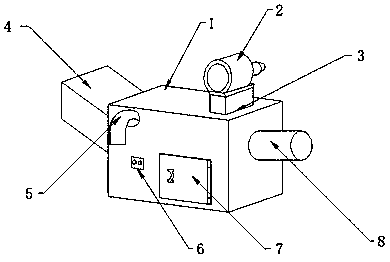
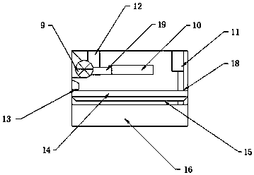
[0017] see Figure 1-3 , the present invention provides a technical solution: a hot blast stove for grain drying, comprising a blast stove box 1, a columnar blower 2 is provided on the top of the blast stove box 1, and a fixed Plate 3, the fixed plate 3 covers the outer surface of the blower 2, and is fixedly connected with the blower 2 by screws, one side of the outer surface of the blower 2 is provided with a dust outlet 5, and the dust outlet 5 runs throug...


PUM


Abstract

The invention discloses a hot-blast stove used for grain drying. The hot-blast stove includes a wind furnace box; the top of the wind furnace box is provided with a cylindrical air blower; the bottomof the air blower is provided with a fixing plate; the fixing plate covers the outer side face of the air blower and fixedly connected to the air blower through screws; one side on the outer surface of the air blower is provided with a dust discharging port; the dust discharging port passes through the internal of the wind furnace box and is welded with the wind furnace box; the bottom of the dustdischarging port is provided with a control panel; the side face of the control panel is provided with a stove door; the end part of the stove door is provided with a cylindrical discharge port; theend part of the wind furnace box is provided with a feeding port; and the feeding port is embedded in the wind furnace box. Through the arrangement of a drying machine in the wind furnace box and theincreasing of a heat absorbing plate at the bottom, the hot-blast stove can rapidly absorb heat to provide high temperature for the drying machine so that the drying speed can be accelerated.

Description

technical field [0001] The invention relates to the technical field of hot blast stoves, in particular to a hot blast stove for grain drying. Background technique [0002] The so-called hot blast stove, of course, refers to the use of direct combustion of fuel, high purification treatment to form hot air, and direct contact with materials to heat, dry or bake. This method reduces fuel consumption by about half compared to steam or other indirect heaters. , without affecting the quality of drying products, it is completely possible to use direct high-purification hot air. Through long-term production practice, people have realized that only by using hot air as a medium and carrier can the heat utilization rate and thermal work be greatly improved. As a result, the traditional electric heat source and steam thermal power have many disadvantages such as a lot of waste of energy, excessive auxiliary equipment, and complicated process during the transportation process. Therefore,...

Claims


Application Information

Patent Timeline
Patent Type & Authority Applications(China)
IPC IPC(8): F26B21/00A23B9/08
CPCF26B21/001A23B9/08F26B21/004F26B2200/06
Inventor 周如彬
Owner 周如彬
Why Eureka
Try Eureka