Energy storage control method and system for grid-connected optical storage and charging system

An energy storage control and optical storage technology, applied in the field of optical storage and charging, can solve the problems of hybrid energy storage battery system control strategy, difficult smooth switching, etc., and achieve the effect of simple and effective control strategy and high engineering application value.

Active Publication Date: 2019-01-29
SHANGHAI POWER ENERGY STORAGE BATTERY SYST ENG TECH
1 Cites 3 Cited by

AI-Extracted Technical Summary

Problems solved by technology

However, the current microgrid system has just started, and smooth switching between off-grid and grid-connected is a major technic...

Abstract

The invention provides an energy storage control method and an energy storage control system for a grid-connected optical storage and charging system. The energy storage control system comprises a mains supply module, wherein the mains supply module is connected with an energy storage module, a photovoltaic power generation module and a user side module respectively, the mains supply module is used for providing a continuous and stable power supply, and the photovoltaic power generation module and the mains supply module are used for photovoltaic grid connection; the energy storage module comprises a plurality of echelon battery energy storage mechanisms and a plurality of new battery energy storage mechanisms; and the user side module comprises a charging pile mechanism and a lighting mechanism. The energy storage control method and the energy storage control system start from the grid-connected optical storage and charging system, fully consider the performance of the photovoltaic power generation module and the energy storage module in the grid-connected optical storage and charging system, reasonably adjust the generated power and power transmission direction of the photovoltaic power generation module according to the amount of electricity consumption of the user side, fully utilize the efficacy of peak-shaving and valley-filling of the energy storage module, and maximizethe generated power of the energy storage module; and the control strategy is simple and effective, and has high engineering application value.

Application Domain

Technology Topic

Image

  • Energy storage control method and system for grid-connected optical storage and charging system
  • Energy storage control method and system for grid-connected optical storage and charging system
  • Energy storage control method and system for grid-connected optical storage and charging system

Examples

  • Experimental program(1)

Example Embodiment

[0053] The present invention will be described in detail below in conjunction with specific embodiments. The following examples will help those skilled in the art to further understand the present invention, but do not limit the present invention in any form. It should be noted that for those of ordinary skill in the art, several changes and improvements can be made without departing from the concept of the present invention. These all belong to the protection scope of the present invention.
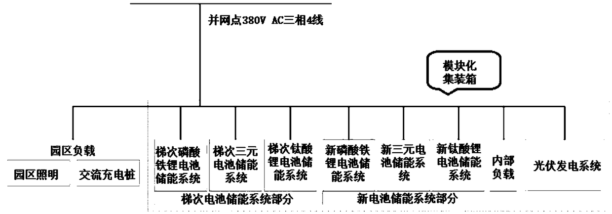
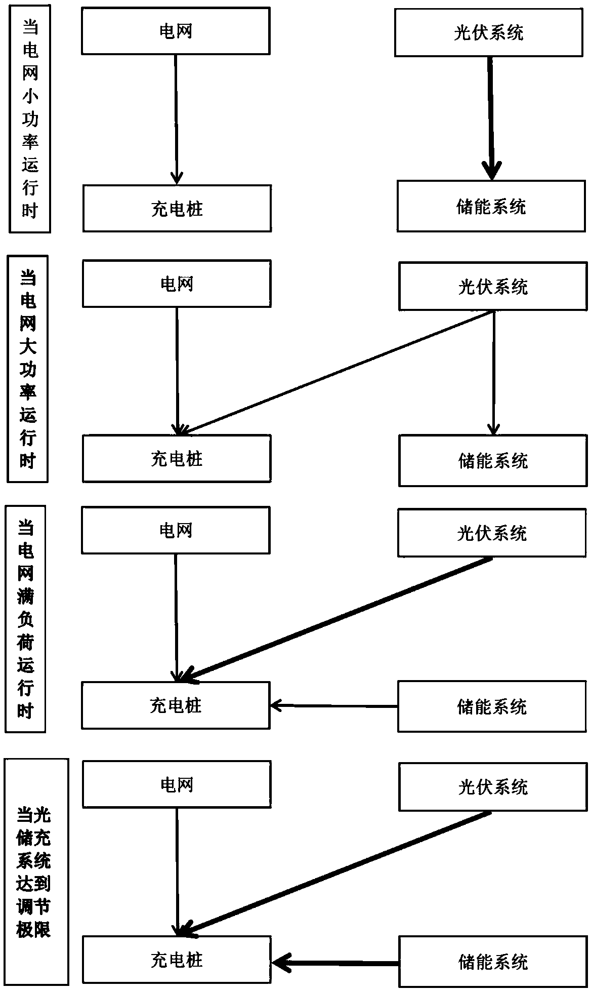
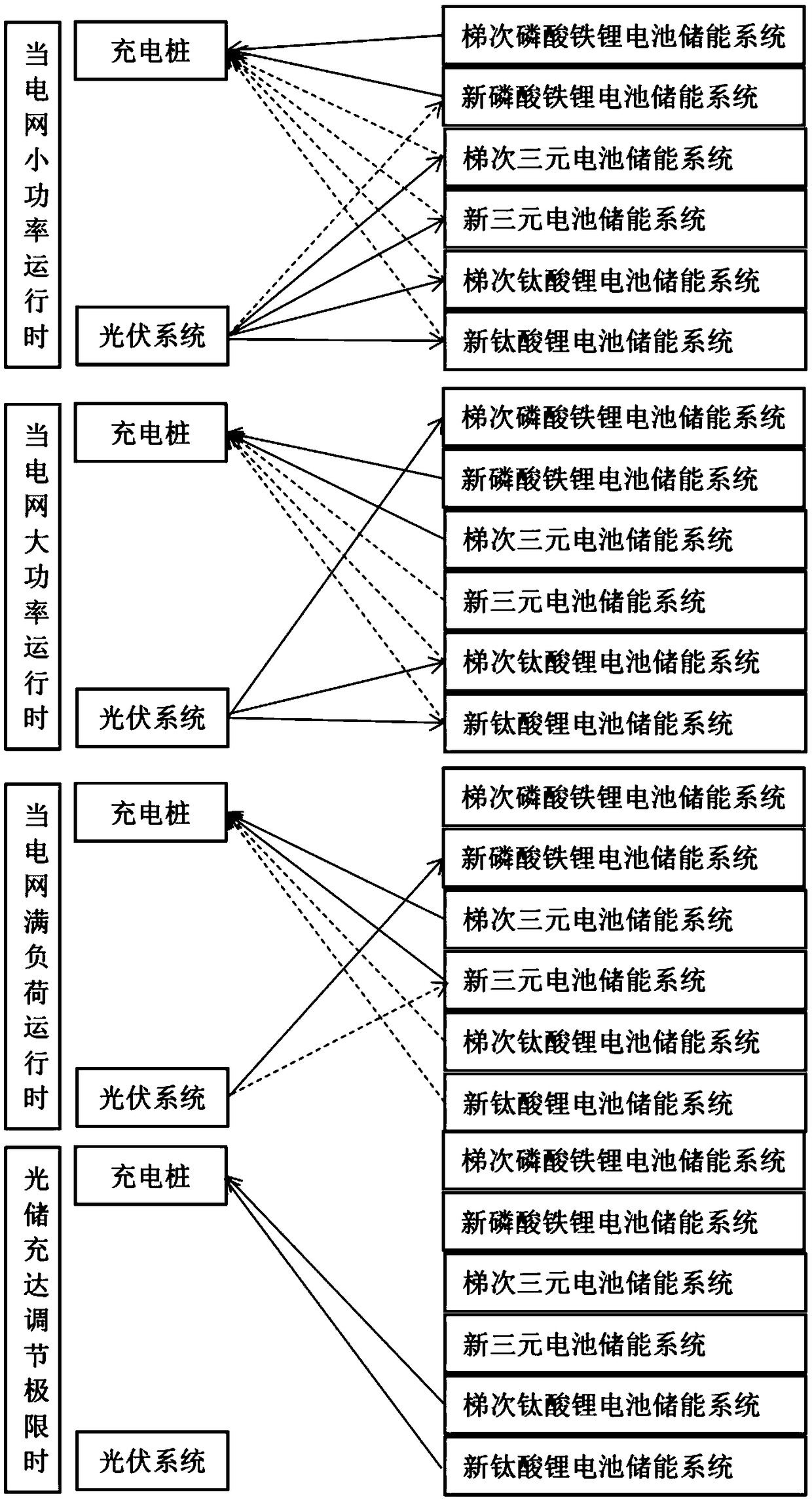
[0054] The purpose of the present invention is to provide a control strategy for grid-connected optical storage and charging and its hybrid energy storage system. Starting from the grid-connected optical storage and charging system, its control strategy is solved; at the same time, it is also suitable for mixed echelon batteries and new batteries. According to the difference of various battery performance, the energy storage system gives a control strategy. The greatest advantage of the present invention lies in the grid-connected use under the premise of maximizing the use of the optical storage system, which ensures the stability and reliability of the long-term operation of the optical storage and charging system.
[0055] A grid-connected optical storage and charging system according to the present invention includes a mains module, an energy storage module, a photovoltaic power generation module, and a user-side module;
[0056] The mains power module is respectively connected to an energy storage module, a photovoltaic power generation module, and a user-side module, the mains power module is used to provide continuous and stable power, and the photovoltaic power generation module and the mains power module are used for photovoltaic grid connection;
[0057] The energy storage module includes multiple cascade battery energy storage mechanisms and multiple new battery energy storage mechanisms;
[0058] The user-side module includes any one or more of a charging pile mechanism and a lighting mechanism.
[0059] Specifically, the cascade battery energy storage mechanism includes any one or more of a new lithium iron phosphate battery energy storage device, a new ternary battery energy storage device, and a new lithium titanate battery energy storage device.
[0060] Specifically, the new battery energy storage mechanism includes any one or more of a new lithium iron phosphate battery energy storage device, a new ternary battery energy storage device, and a new lithium titanate battery energy storage device.
[0061] According to an energy storage control method of a grid-connected optical storage and charging system provided by the present invention, the grid-connected optical storage and charging system includes a mains module, an energy storage module, a photovoltaic power generation module, and a user-side module;
[0062] The mains power module is respectively connected to an energy storage module, a photovoltaic power generation module, and a user-side module, the mains power module is used to provide continuous and stable power, and the photovoltaic power generation module and the mains power module are used for photovoltaic grid connection;
[0063] The energy storage module includes multiple cascade battery energy storage mechanisms and multiple new battery energy storage mechanisms;
[0064] The user-side module includes any one or more of a charging pile mechanism and a lighting mechanism;
[0065] When the grid of the mains module is running at low power, the grid gives priority to powering the charging pile; at the same time, the discharge power of the energy storage module is reduced on the basis of meeting the peak and valley filling, and the charging power is increased. The photovoltaic power generation module gives priority to the energy storage module;
[0066] Specifically, when the energy storage module reaches the upper limit of charging, the photovoltaic power generation of the photovoltaic power generation module is stopped or restricted.
[0067] Specifically, when the grid is operating at high power, the photovoltaic power generation module charges the charging pile mechanism, and at the same time increases the discharge power of the energy storage module and reduces the charging power on the basis of meeting peak shaving and valley filling. The photovoltaic power generation module also supplies power to the energy storage module. ;
[0068] Specifically, when the power grid is running at full load, first the photovoltaic power generation module generates full load to supply the charging pile mechanism, and at the same time, the discharge power of the energy storage module is increased on the basis of meeting peak shaving and valley filling, and the charging power is reduced. The photovoltaic power generation module does not store energy. Module power supply;
[0069] Specifically, when the optical storage and charging module reaches the adjustment limit, the photovoltaic power generation module and the energy storage module generate power at full load and supply the charging pile mechanism, while gradually cutting out the controllable charging pile mechanism.
[0070] According to an energy storage control method of a grid-connected optical storage and charging system provided by the present invention, the grid-connected optical storage and charging system includes a mains module, an energy storage module, a photovoltaic power generation module, and a user-side module;
[0071] The mains power module is respectively connected to an energy storage module, a photovoltaic power generation module, and a user-side module, the mains power module is used to provide continuous and stable power, and the photovoltaic power generation module and the mains power module are used for photovoltaic grid connection;
[0072] The energy storage module includes multiple cascade battery energy storage mechanisms and multiple new battery energy storage mechanisms;
[0073] The user-side module includes any one or more of a charging pile mechanism and a lighting mechanism;
[0074] The charging control strategy is that the photovoltaic power generation modules equally charge the energy storage modules that are not in a discharged state;
[0075] The discharge control strategy is based on the difference in the discharge power and calorific value of the energy storage module, first discharge the cascade battery energy storage mechanism with low power and large heat generation, and then discharge with the new battery energy storage mechanism with low power and high heat generation, and then use The battery energy storage mechanism is used to discharge the high-power step with low heat generation, and finally the new battery energy storage mechanism with high-power low heat generation is discharged.
[0076] Specifically, when a certain energy storage module reaches the upper limit of charging, automatically stop the charging of the energy storage module;
[0077] Specifically, when the photovoltaic power generation module has conditions to charge the energy storage module, the undischarged hybrid energy storage module selects charging or standing still according to the photovoltaic power generation capacity;
[0078] The hybrid energy storage battery mechanism mainly composed of the ladder battery energy storage mechanism and the new battery energy storage mechanism. With the increase of discharge power, the discharge sequence is: ladder lithium iron phosphate battery energy storage mechanism, new lithium iron phosphate battery energy storage mechanism, Echelon ternary battery energy storage mechanism, new ternary battery energy storage mechanism, echelon lithium titanate battery energy storage mechanism, and new lithium titanate battery energy storage mechanism.
[0079] In the case of grid connection, when the demand for electricity is low, the grid supplies power to the charging pile mechanism, and the photovoltaic power generation module supplies power to the energy storage module; when the demand for electricity increases, the grid and the photovoltaic power generation module supply power to the charging pile mechanism at the same time; the demand for electricity is further When it increases, the power grid, photovoltaic power generation modules and energy storage modules will supply power to the charging pile mechanism at the same time; when the electricity demand exceeds the light storage charging load, the charging pile load will be gradually cut off.
[0080] Among them, when the power grid is running at low power, the photovoltaic power generation module will give priority to charging the hybrid energy storage module that is not in the discharged state. At the same time, the cascade battery energy storage mechanism with low power and large heat generation should be discharged first, and then low power heat generation The large new battery energy storage mechanism is discharged, and then the battery energy storage mechanism is discharged in the steps of high power and small heat generation, and finally the new battery energy storage mechanism is discharged with high power and small heat generation;
[0081] Among them, when the power grid is running at high power, the charging pile needs to be mixed with energy storage modules to input a larger power, and it should be discharged with a new battery energy storage mechanism with low power and large heat, and then used in cascades with high power and low heat. The battery energy storage mechanism is discharged, and finally the new battery energy storage mechanism with high power and low heat is discharged;
[0082] Among them, when the grid is running at full load, the photovoltaic power generation module stops charging the energy storage module. At this time, the battery energy storage mechanism should be used to discharge the energy in a step with high power and low heat, and finally the new battery with high power and low heat is stored. Mechanism discharge; among them, when the optical storage and charging system reaches the regulation limit, the new battery energy storage mechanism with high power and low heat is discharged.
[0083] In the optical storage and charging system, there is a monitoring unit EMS (Energy Control System), and the function of the monitoring unit EMS is to detect the conditions of the power consumption end and the power generation end, and reasonably adjust the charge and discharge power. The grid power setting in the control strategy is through a preset value, and it is clear that when the power is less than a certain set value, it is low-power operation.
[0084] According to the present invention, there is provided a computer-readable storage medium storing a computer program, which implements the steps of the above method when the computer program is executed by a processor.
[0085] Such as figure 1 As shown, the present invention includes four parts: mains power, energy storage system, photovoltaic system and user side. Among them, the energy storage system includes multiple cascade battery energy storage systems and multiple new battery energy storage systems.
[0086] Furthermore, the cascade battery energy storage system includes the cascade lithium iron phosphate battery energy storage system, the cascade ternary battery energy storage system, and the cascade lithium titanate battery energy storage system;
[0087] Further, the new battery energy storage system includes a new lithium iron phosphate battery energy storage system, a new ternary battery energy storage system, and a new lithium titanate battery energy storage system.
[0088] Such as figure 2 As shown, the control strategy of the optical storage and charging system is as follows:
[0089] When the grid is operating at low power, the grid gives priority to powering the charging pile; at the same time, on the basis of meeting peak shaving and valley filling, the discharge power of the energy storage system is reduced, and the charging power is increased. The photovoltaic system gives priority to the energy storage system;
[0090] Further, when the energy storage system reaches the upper limit of charging, stop or limit photovoltaic power generation;
[0091] When the power grid is running at high power, the photovoltaic system charges the charging pile, and at the same time increases the discharge power of the energy storage system and reduces the charging power on the basis of satisfying peak shaving and valley filling. The photovoltaic system also supplies power to the energy storage system;
[0092] When the grid is running at full load, the photovoltaic system first generates full-load power to supply the charging pile, and at the same time increases the discharge power of the energy storage system on the basis of peak shaving and valley filling, and reduces the charging power. The photovoltaic system does not supply power to the energy storage system;
[0093] When the optical storage and charging system reaches the regulation limit, the photovoltaic system and the energy storage system generate electricity at full load to supply the charging pile, and at the same time gradually cut out the controllable charging pile load.
[0094] Such as image 3 As shown, a control strategy between hybrid energy storage battery systems is as follows:
[0095] Its charging control strategy is to use the photovoltaic system to evenly charge the hybrid energy storage system that is not in a discharge state;
[0096] Further, when a certain energy storage system reaches the upper limit of charging, its EMS automatically stops the charging function;
[0097] The discharge control strategy is based on the difference in the discharge power and calorific value of the energy storage system, first discharge the cascade battery energy storage system with low power and large calorific value, then discharge with the new battery energy storage system with low power and large calorific value, and then The battery energy storage system is used to discharge the cascade of high power with a small amount of heat, and finally discharged with a new battery energy storage system with a small amount of heat.
[0098] Further, as the discharge power of the hybrid energy storage battery system increases, its discharge sequence is: echelon lithium iron phosphate battery energy storage system, new lithium iron phosphate battery energy storage system, echelon ternary battery energy storage system, new Ternary battery energy storage system, echelon lithium titanate battery energy storage system, new lithium titanate battery energy storage system.
[0099] When the grid is running at low power, the photovoltaic system will give priority to charging the hybrid energy storage system that is not in a discharged state. At the same time, the discharge sequence of the energy storage system is the ladder lithium iron phosphate battery energy storage system, the new lithium iron phosphate battery energy storage system, and the ladder Ternary battery energy storage system, new ternary battery energy storage system, echelon lithium titanate battery energy storage system, new lithium titanate battery energy storage system;
[0100] When the power grid is running at high power, the charging pile requires a hybrid energy storage system with a larger power input, and the discharge sequence of the energy storage system is the new lithium iron phosphate battery energy storage system, the cascade ternary battery energy storage system, and the new ternary energy storage system. Battery energy storage system, echelon lithium titanate battery energy storage system, new lithium titanate battery energy storage system;
[0101] When the grid is running at full load, the photovoltaic system stops charging the energy storage system, and the discharge sequence of the energy storage system is the cascade ternary battery energy storage system, the new ternary battery energy storage system, the cascade lithium titanate battery energy storage system, New lithium titanate battery energy storage system;
[0102] When the optical storage and charging system reaches the regulation limit, the discharge sequence of the energy storage system is the echelon lithium titanate battery energy storage system and the new lithium titanate battery energy storage system.
[0103] Those skilled in the art know that, in addition to implementing the system, device and various modules provided by the present invention in a purely computer-readable program code manner, it is entirely possible to program the system, device and various modules provided by the present invention by logically programming method steps. The same program is implemented in the form of logic gates, switches, application specific integrated circuits, programmable logic controllers, and embedded microcontrollers. Therefore, the system, device and various modules provided by the present invention can be regarded as a kind of hardware component, and the modules included in it for implementing various programs can also be regarded as the structure within the hardware component; Modules for realizing various functions can be regarded as both software programs for realizing methods and structures within hardware components.
[0104] The specific embodiments of the present invention have been described above. It should be understood that the present invention is not limited to the above specific embodiments, and those skilled in the art can make various changes or modifications within the scope of the claims, which does not affect the essence of the present invention. In the case of no conflict, the embodiments of the present application and the features in the embodiments can be combined with each other arbitrarily.

PUM

no PUM

Description & Claims & Application Information

We can also present the details of the Description, Claims and Application information to help users get a comprehensive understanding of the technical details of the patent, such as background art, summary of invention, brief description of drawings, description of embodiments, and other original content. On the other hand, users can also determine the specific scope of protection of the technology through the list of claims; as well as understand the changes in the life cycle of the technology with the presentation of the patent timeline. Login to view more.

Similar technology patents

Centralized generating set of renewable energy source

InactiveCN102195298AReduce control objectsSimple control strategySingle network parallel feeding arrangementsElectric energyPower grid
Owner:HARBIN ENG UNIV

Steering device of underwater vehicle

InactiveCN105059518ASimple structureSimple control strategySteering ruddersElectric machineryPropeller
Owner:DALIAN MARITIME UNIVERSITY

Variable valve lift mechanism

InactiveCN103850744AGood linear output performanceSimple control strategyValve arrangementsMachines/enginesRocker armLinear control
Owner:SOUTH CHINA UNIV OF TECH

Classification and recommendation of technical efficacy words

  • Simple control strategy
  • High engineering application value

Simplification control method of parallel connection type active electric power filter

InactiveCN107732915ASimple control strategyReduce complexityActive power filteringAc network to reduce harmonics/ripplesFull bridge inverterPower grid
Owner:JIANGSU UNIV

Electromagnetic jaw clutch structure

PendingCN107975546ASimple control strategyMagnetically actuated clutchesClutchVariator
Owner:四川阿尔特新能源汽车有限公司

Optimization method of renewable energy source distribution type power generation operation mode

InactiveCN102799952AImprove practical operabilityHigh engineering application valueForecastingSystems intergating technologiesRenewable energyAnnual average
Owner:CHINA ELECTRIC POWER RES INST +1

Menu-type design method based on optimized information integrated GEO satellite control system

ActiveCN105253330AVersatileHigh engineering application valueCosmonautic vehiclesInstruments for comonautical navigationSun sensorSetting time
Owner:CHINA ACADEMY OF SPACE TECHNOLOGY
Why Eureka
Try Eureka