
Compensation method and device for rotor position of permanent magnet synchronous generator

A generator rotor and rotor position technology, applied in the direction of synchronous generator control, generator circuit layout control, generator control, etc., can solve the problem of the reduction of power generation efficiency of permanent magnet synchronous generators, the inability to achieve maximum torque-current ratio control, Unable to estimate the position of the pole rotor and other issues

Active Publication Date: 2019-01-29
BEIJING GOLDWIND SCI & CREATION WINDPOWER EQUIP CO LTD
View PDF4 Cites 4 Cited by
  • Summary
  • Abstract
  • Description
  • Claims
  • Application Information

AI Technical Summary

Problems solved by technology

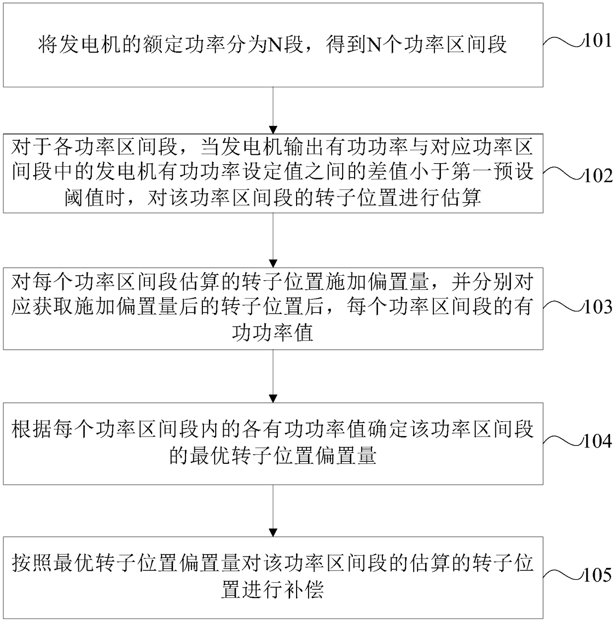
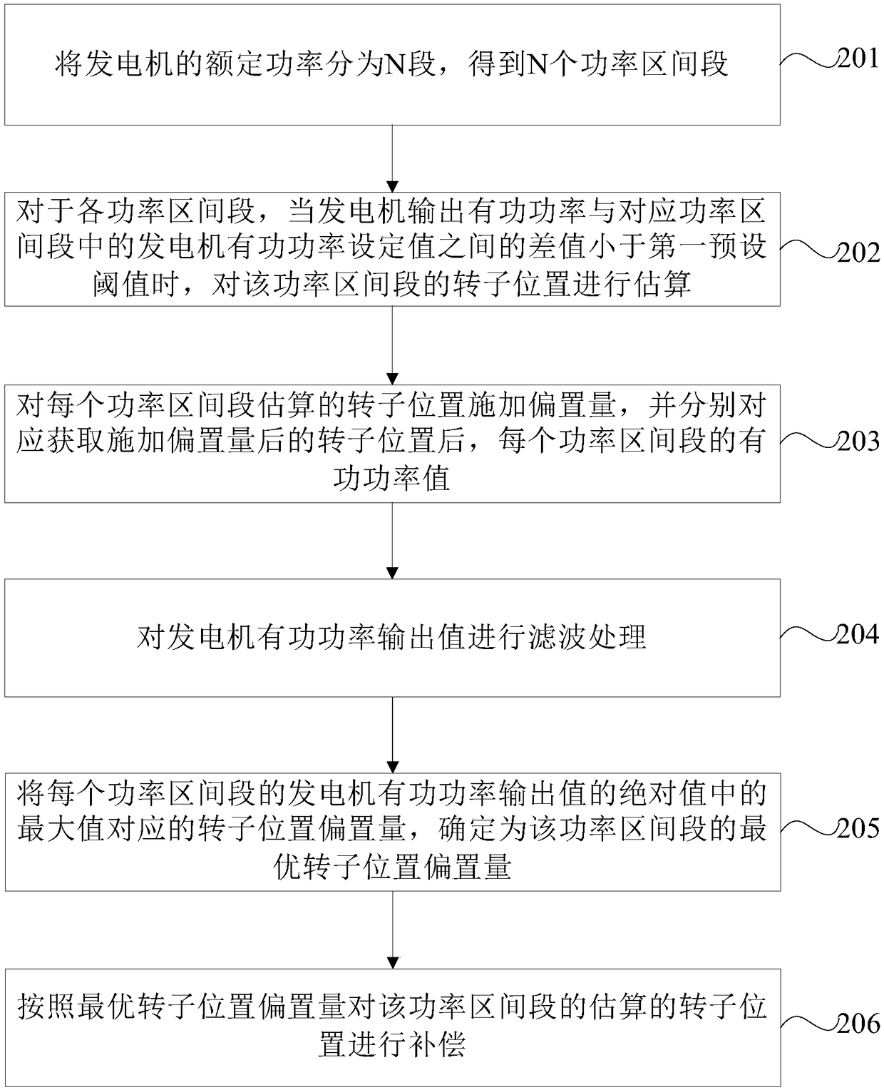
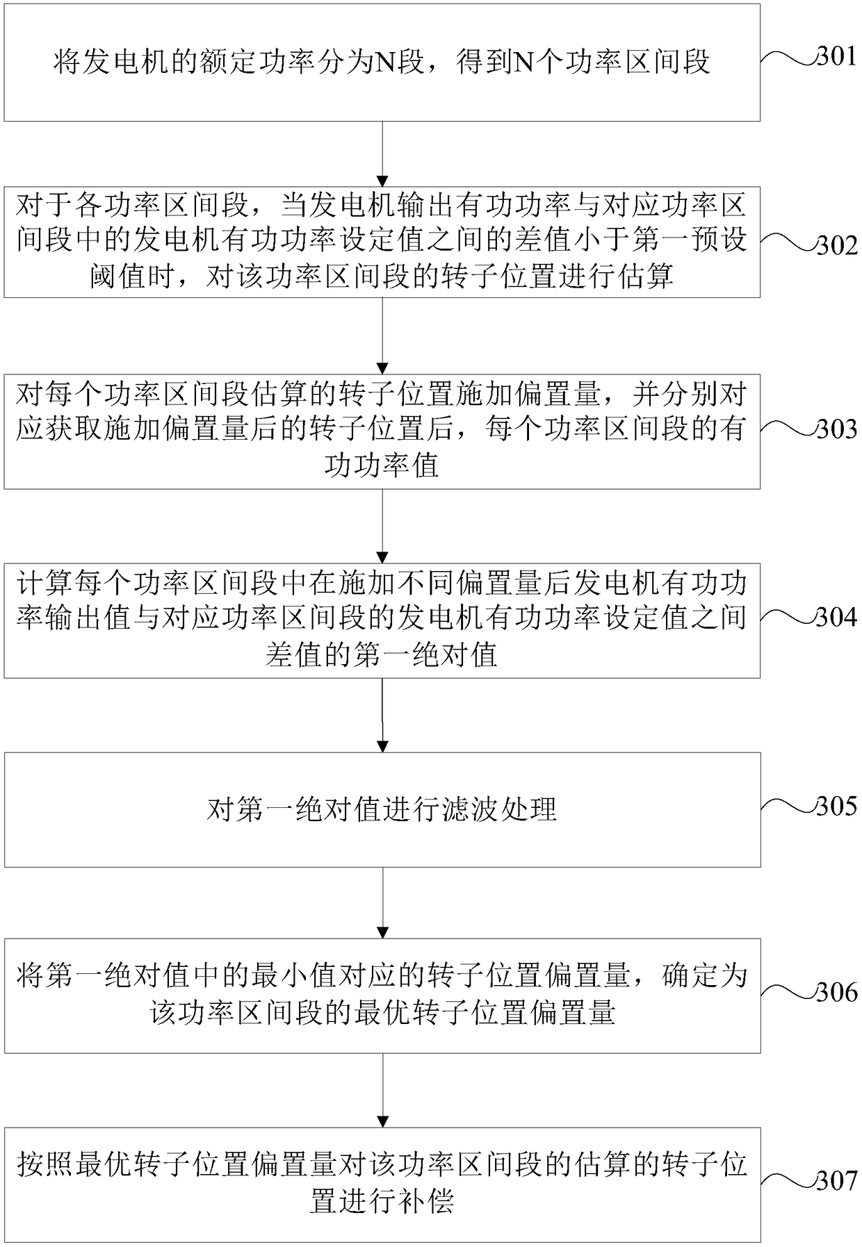
[0005] Embodiments of the present invention provide a method and device for compensating the rotor position of a permanent magnet synchronous generator. There is a deviation between the reactive current and the actual value, and then the maximum torque-current ratio control cannot be realized, which eventually leads to the technical problem that the power generation efficiency of the permanent magnet synchronous generator is reduced

Method used


Image

  • Compensation method and device for rotor position of permanent magnet synchronous generator
  • Compensation method and device for rotor position of permanent magnet synchronous generator
  • Compensation method and device for rotor position of permanent magnet synchronous generator

Examples


Embodiment Construction

[0029] In order to make the purpose, technical solutions and advantages of the embodiments of the present invention clearer, the technical solutions in the embodiments of the present invention will be clearly and completely described below in conjunction with the drawings in the embodiments of the present invention. Obviously, the described embodiments It is a part of embodiments of the present invention, but not all embodiments. Based on the embodiments of the present invention, all other embodiments obtained by persons of ordinary skill in the art without making creative efforts belong to the protection scope of the present invention.

[0030] It should be understood that the term "and / or" used herein is only an association relationship describing associated objects, which means that there may be three relationships, for example, A and / or B, which may mean that A exists alone, and A and B exist simultaneously. B, there are three situations of B alone. In addition, the chara...


PUM


Abstract

The invention provides a compensation method and device for the rotor position of a permanent magnet synchronous generator. The compensation method comprises the steps of dividing the rated power of the generator into N segments to obtain N power interval sections; for each power interval section, when the difference between the output active power of the generator and an active power set value ofthe generator in the corresponding power interval section is less than a first preset threshold, estimating the rotor position of the power interval section; applying offset to the estimated rotor position of each power interval section, and correspondingly obtaining an active power value of each power interval section after the rotor position with the applied offset is obtained, wherein the active power value includes a converter network side port active power output value or a generator active power output value; determining the optimal rotor position offset of each power interval section according to each active power value in the power interval section; and compensating the estimated rotor position of the power interval section according to the optimal rotor position offset.

Description

technical field [0001] The embodiments of the present invention relate to the technical field of wind power generation, in particular to a method and device for compensating the rotor position of a permanent magnet synchronous generator. Background technique [0002] With the continuous improvement of CNC machine tool technology for high precision and high dynamic performance requirements, permanent magnet synchronous generators are widely used in the field of wind power generation due to their simple structure, high efficiency, good controllability, and wide speed range. Vector control technology and direct torque control technology are commonly used control technologies for permanent magnet synchronous generator control systems. Both vector control technology and direct torque control technology need to obtain the pole rotor position in the permanent magnet synchronous generator, which is used to convert the three-phase current in the three-phase coordinate system into the...

Claims


Application Information

Patent Timeline
Patent Type & Authority Applications(China)
IPC IPC(8): H02P21/18H02P9/00H02P103/20H02P101/15
CPCH02P9/009H02P21/18H02P2101/15H02P2103/20
Inventor 高瑞
Owner BEIJING GOLDWIND SCI & CREATION WINDPOWER EQUIP CO LTD
Learn More