Movable skid-mounted type organic solid waste treatment device

A technology for organic solid waste and treatment equipment, which is applied in sludge treatment, water/sludge/sewage treatment, sludge treatment through temperature control, etc. It can solve the problems that restrict the promotion and application of smoldering technology, and achieve convenience in situ The effect of off-site processing, low energy consumption, easy transportation and installation

Active Publication Date: 2019-02-01
JIANGSU DDBS ENVIRONMENT REMEDIATION
View PDF10 Cites 4 Cited by
  • Summary
  • Abstract
  • Description
  • Claims
  • Application Information

AI Technical Summary

Problems solved by technology

Although the smoldering technology is more advanced than the traditional treatment technology, so far, except for the pilot equipment developed by the applicant, there is no smoldering treatment equipment applicable to actual projects in China, which seriously restricts Promotion and application of smoldering technology in the field of oil sludge treatment

Method used


Image

  • Movable skid-mounted type organic solid waste treatment device
  • Movable skid-mounted type organic solid waste treatment device
  • Movable skid-mounted type organic solid waste treatment device

Examples


Embodiment 1

[0026] Example 1: In situ and ex situ soil thermal desorption restoration.

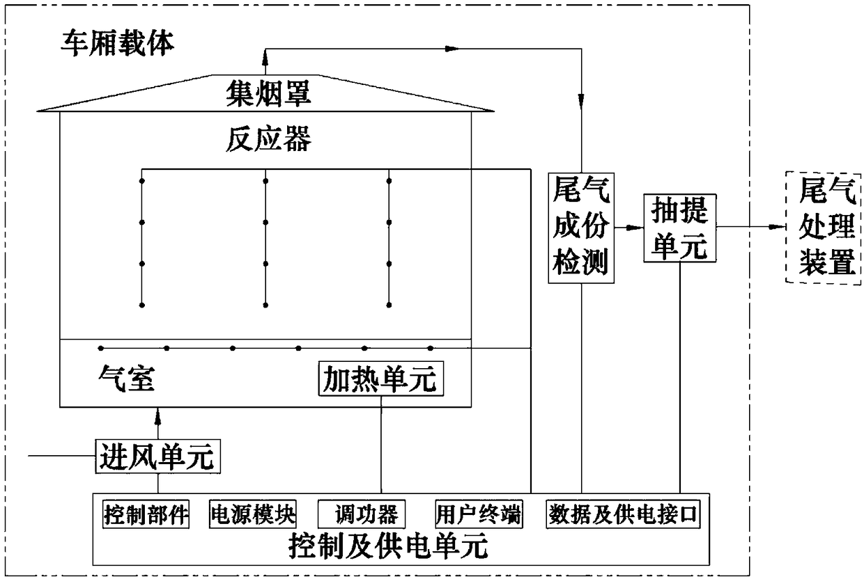
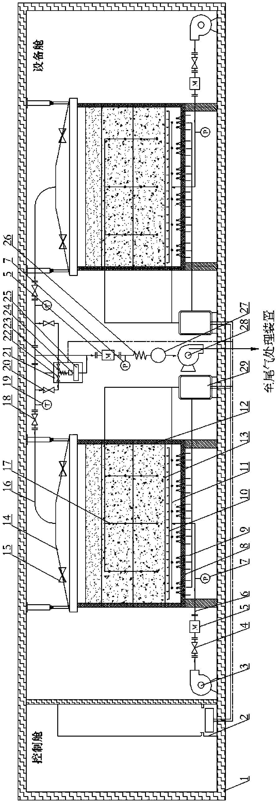
[0027] Use a vehicle to transport the device to the site and hoist it on a flat ground, and connect it to an external power source. The organic matter-contaminated soil that needs to be treated is packed in the reactor 12, according to the attached image 3As shown, each component unit is installed; according to the soil pollution component analysis report, the gas chamber temperature is set at the user terminal of the control and power supply unit 2, generally slightly higher than the highest pollutant boiling point temperature. Start the equipment, the air intake unit will deliver fresh air to the inside of the air chamber, and form a certain positive pressure inside, the heating unit 9 will heat the air inside the air chamber to the set temperature, and the control and power supply unit 2 will The collected temperature data controls the power of the heating unit 9, so that the temperature inside t...

Embodiment 2

[0028] Example 2: Utilize smoldering technology to treat petroleum pollutants (oil sludge).

[0029] Smoldering technology is a technology that uses organic pollutants in soil as self-sustaining fuel to carry out soil remediation through the principle of smoldering. The device can use smoldering technology to dispose of petroleum pollutants (oil sludge) in situ, such as tank bottom sludge and oil sludge near oil wells. Before the treatment, the petroleum pollutants (sludge) to be treated and the clean sand are uniformly stirred in a certain proportion, and the stirred petroleum pollutants (sludge) are put into the reactor 12 to ensure that the inside of the reactor 12 is smoldering Reaction continues, and avoids reactor 12 inside to produce naked flame, covers one deck clean sand above reactor 12 internal polluted soil (oil sludge), according to attached image 3 Install each component unit as shown. Start the equipment, the air intake unit will deliver fresh air to the insi...


PUM


Abstract

The invention discloses a movable skid-mounted type organic solid waste treatment device. The movable skid-mounted type organic solid waste treatment device comprises a control and power supply unit,an air inlet unit, an air chamber, a heating unit, a reactor, a smoke collecting hood, a tail gas component detection unit and an extraction unit. The air inlet unit conveys the fresh air to the air chamber, the heating unit heats the air in the air chamber to enable the temperature to be equal to the appropriate temperature, the organic matter in soil in the reactor can evaporate, or petroleum pollutants (oil sludge) can smolder, the tail gas is collected by the smoke collecting hood, the tail gas component detection unit preliminarily detects the components in the tail gas, the tail gas is conveyed by an extraction system to a tail gas treatment device, and therefore efficient and energy-saving treatment of the organic solid waste is achieved. Temperature sensors are installed in the airchamber, installed on the surface of the heating unit and installed in the reactor, the power of the heating unit and the air inlet quantity are controlled to achieve the control over the temperatureof the interior of the air chamber and the temperature of the interior of the treated solid waste, and therefore the whole process control is achieved. The whole device is integrated in a compartmentcarrier, can be moved and mounted in a skid mode, is easy to transport and hoist and achieves the safe, efficient, energy-saving and environmentally friendly treatment effects.

Description

technical field [0001] The invention relates to the technical field of organic solid waste disposal, in particular to a mobile skid-mounted organic solid waste treatment device. Background technique [0002] Thermal desorption is an effective way to deal with soil contaminated by organic matter. It refers to heating the organic pollutants in the soil to a sufficient temperature through direct or indirect heat exchange, and adjusting the heating temperature and residence time to selectively convert the pollutants from one phase to the other. It is another phase, so that organic pollutants can be volatilized or separated from the polluted medium, and there is no damage to organic pollutants in the repair process. Generally speaking, it can be divided into in-situ thermal desorption and ex-situ thermal desorption. attached. The existing ectopic thermal desorption equipment has complex structure, large volume, heavy weight, and long on-site installation and commissioning cycle,...

Claims


Application Information

Patent Timeline
Patent Type & Authority Applications(China)
IPC IPC(8): B09C1/06C02F11/13C02F11/00C02F11/18
CPCB09C1/06C02F11/00C02F11/12C02F11/18
Inventor 李龙雷大鹏陈晓丽沈诣赵长志高连
Owner JIANGSU DDBS ENVIRONMENT REMEDIATION
Why Eureka
Try Eureka