Material transfer device

A material transfer technology, applied in the field of material transfer devices, can solve the problems of low material processing efficiency and achieve the effects of improving processing efficiency, speeding up material transfer speed, and speeding up processing tempo

Pending Publication Date: 2019-02-01
长沙凯中电气科技有限公司
View PDF0 Cites 0 Cited by
  • Summary
  • Abstract
  • Description
  • Claims
  • Application Information

AI Technical Summary

Problems solved by technology

[0004] Therefore, the technical problem to be solved by the present invention is to overcome the technical defect of low material processing efficiency caused by the large space occupation of the manipulator in the prior art, thereby providing a material transfer device with fast material transfer speed and simple structure

Method used


Image

  • Material transfer device

Examples


specific Embodiment approach

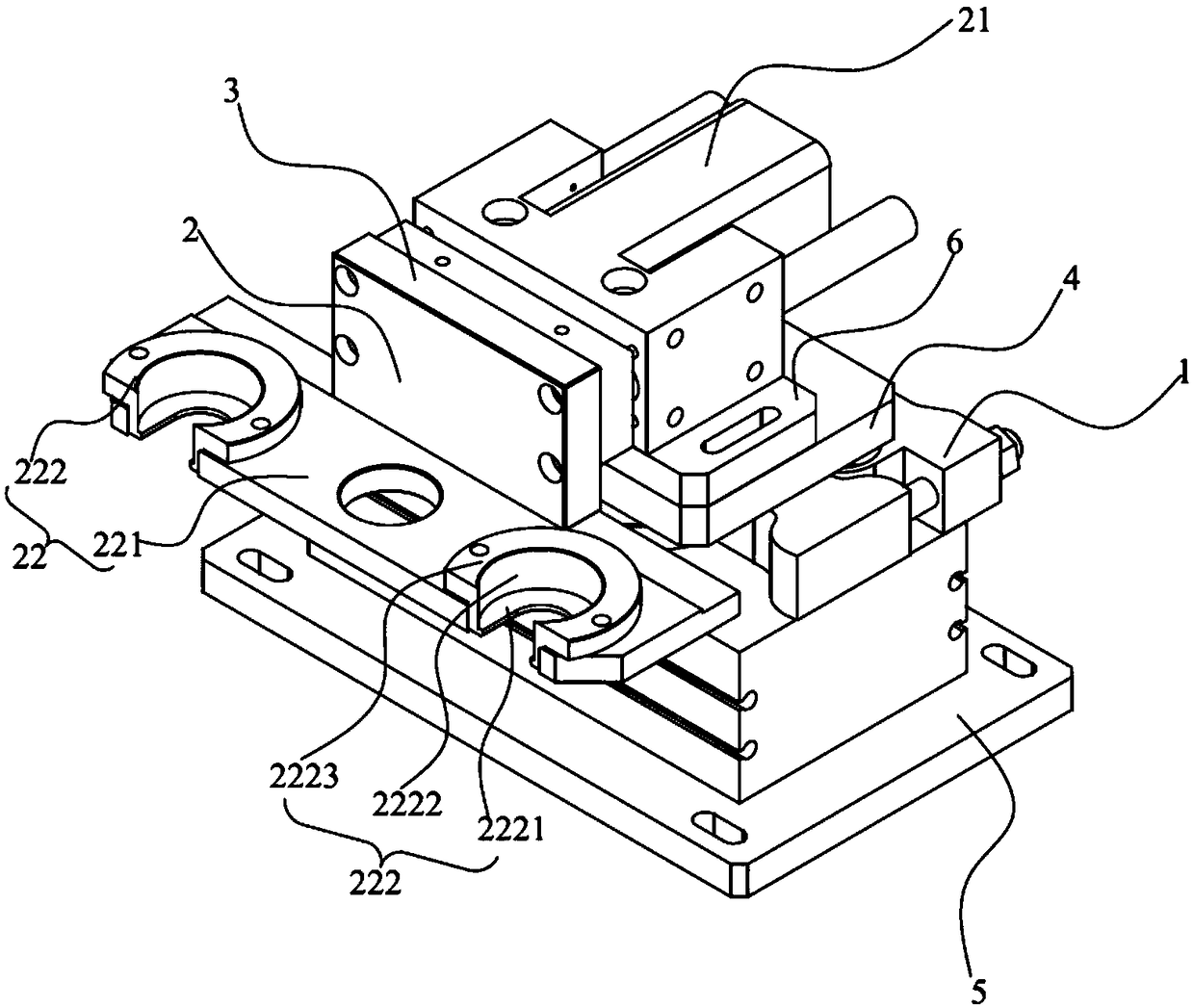
[0031] Such as figure 1 A specific implementation of the shown material transfer device includes:

[0032] The rotating assembly 1 and the moving assembly 2, which are relatively fixed, are arranged between two adjacent stations. The moving assembly 2 is driven by power to move towards the material output direction of the previous station to receive the previous station. The telescopic structure 21 of the materials output by the station, the rotating assembly 1 has the function of reciprocating between the two stations under power drive, so as to transport the materials received by the moving assembly 2 to the next station rotating structure.

[0033] The above-mentioned material transfer device is arranged between two adjacent stations, and includes a relatively fixed rotating assembly 1 and a moving assembly 2. The rotating assembly 1 can reciprocate between two adjacent stations. When the rotating assembly 1 reciprocates , the moving assembly 2 can reciprocate along with ...


PUM


Abstract

The invention provides a material transfer device. The material transfer device comprises a rotating assembly and a moving assembly which are relatively and fixedly arranged between two adjacent working positions. The moving assembly is provided with a telescopic structure, and the rotating assembly is provided with a rotating structure, wherein the telescopic structure is driven by power to movetowards the material output direction of the previous working position so as to receive materials output from the previous working position; and the rotating structure is driven by power to reciprocate between the two working positions so as to transfer the materials received by the moving assembly to the next working position. When the rotating assembly rotates reciprocally, the moving assembly can rotate reciprocally together with the rotating assembly. The telescopic structure of the moving assembly can receive the materials output from the previous working position in the extension and retraction direction. After the materials are received, the telescopic structure retracts again, and then the rotating assembly rotates to transfer the materials to the next working position, so that material transfer between the adjacent two working positions is realized. By means of the material transfer mode, full-automatic material transfer is achieved, the material transfer speed is high, and the material processing efficiency is improved.

Description

technical field [0001] The invention relates to the field of material transportation, in particular to a material transfer device. Background technique [0002] The commutator, commonly known as the commutator, is a part of the DC permanent magnet series motor to allow the motor to continue to rotate. It usually includes an insulating sleeve and a commutator piece sleeved on the outer periphery of the insulating sleeve. When the commutator is processed, it is necessary to bend the contact pins extending from the commutator piece after the commutator piece is fixed on the outer periphery of the insulating sleeve. Bending, based on the existing characteristics of the existing commutator and the existing forming technology, when bending the contact pin, it is necessary to adopt a multi-step bending and forming process to perform secondary processing on the commutator. The existing bending The steps of folding and forming processing generally include hook unfolding, hook bendin...

Claims


Application Information

Patent Timeline
Patent Type & Authority Applications(China)
IPC IPC(8): B21F1/00B21F23/00H01R43/06
CPCB21F1/00B21F23/00H01R43/06
Inventor 冯剑锋邓贵兵
Owner 长沙凯中电气科技有限公司
Why Eureka
Try Eureka