
Underwater ventilation cavity assisted high-pressure water jet cutting device

A high-pressure water jet and cutting device technology, applied in the direction of explosion generation device, abrasive feeding device, used abrasive processing device, etc., can solve the problems of reduced cutting efficiency, unstable high-pressure pump, high energy consumption, etc. Achieve the effect of neat cutting surface, guarantee of safety and high water jet speed

Inactive Publication Date: 2019-02-01
HARBIN ENG UNIV
View PDF5 Cites 5 Cited by
  • Summary
  • Abstract
  • Description
  • Claims
  • Application Information

AI Technical Summary

Problems solved by technology

However, cutting under water is affected by water resistance and pressure difference resistance, and the cutting efficiency will be greatly reduced. Compared with cutting in air, cutting in water requires a higher supply pressure, resulting in greater energy consumption, which poses a challenge to the high-pressure pump. Higher requirements also bring instability, so it is urgent and necessary to study how to reduce the resistance of underwater water cutting, which can not only reduce costs and obtain greater benefits, but also improve the stability and service life of equipment

Method used


Image

  • Underwater ventilation cavity assisted high-pressure water jet cutting device
  • Underwater ventilation cavity assisted high-pressure water jet cutting device
  • Underwater ventilation cavity assisted high-pressure water jet cutting device

Examples


Embodiment Construction

[0017] The present invention will be further described below in conjunction with accompanying drawing:

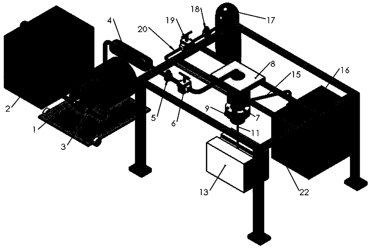
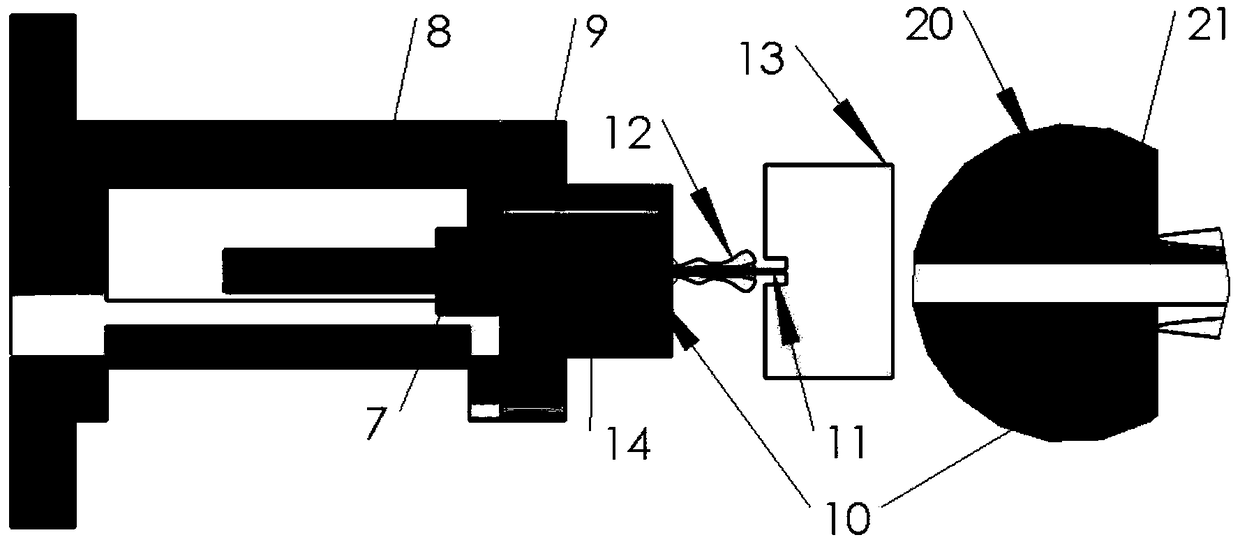
[0018] as attached figure 1 Shown is the system structure diagram of the present invention, attached figure 2 Shown is a partially enlarged view of the water injection part of the present invention. An underwater ventilation cavitation assisted high-pressure water jet cutting device, including a high-pressure water pump 1, a water tank 2, a high-pressure water pipe 3, an accumulator 4, a pressure regulating valve 5, a flow meter 6, a water pipe joint 7, and a water knife fixed slider 8 , water jet reactor 9, ruby ​​nozzle 10, high-speed water jet 11, air bubble 12, workpiece to be cut 13, frosted mixing pipe 14, frosted delivery pipe 15, frosted 16, high-pressure gas cylinder 17, gas pressure regulating valve 18 , gas 19, air pipe 20, air cavity 21, water jet CNC guide rail mounting frame 22; the high-pressure water tank is located on the far left side of the device, and...


PUM


Abstract

The invention belongs to the field of underwater cold cutting, and particularly relates to an underwater ventilation cavity assisted high-pressure water jet cutting device. A high-pressure water tank,a high-pressure water pump, an energy accumulator, a pressure regulating valve, a flowmeter, a water pipe connector, a water cutter generator and a ruby nozzle are sequentially connected through a high-pressure water pipe; water in the high-pressure water tank forms a high-speed water jet flow at the ruby nozzle through the high-pressure water pipe; grinding sand is located on a water cutter numerical control guide rail installation frame and is connected with the water pipe connector through a grinding sand conveying pipe and a grinding and mixing pipe sequentially; a high-pressure gas cylinder, a gas pressure regulating valve, a gas flowmeter, a gas pipe, a gas cavity and an air bubble are sequentially connected through a pipeline; gas and the high-speed water jet flow are ejected ontoa workpiece to be cut so as to cut the workpiece; and the air bubble packs the jet flow at the position close to an outlet. According to the underwater ventilation cavity assisted high-pressure waterjet cutting device provided by the invention, the workpiece cannot be locally heated so as to be prevented from being deformed, no molten slags and chemical reaction is generated to cause toxic substances, the cutting accuracy is high, the cutting surfaces are in order, and the equipment performance and the service life are improved.

Description

technical field [0001] The invention belongs to the field of underwater cold cutting, and in particular relates to an underwater ventilation cavitation assisted high-pressure water jet cutting device. Background technique [0002] In recent years, my country's infrastructure technology has developed rapidly. Many bridges across rivers and seas and hydropower dams have been built, and several offshore drilling platforms have been built in the South China Sea to legally exercise maritime rights and interests. However, these operations inevitably require underwater operations. Underwater rock soil or metal cutting and other problems, underwater cutting is not only difficult for personnel to operate, it is not easy to burn in water, there is pressure difference resistance, water is easy to conduct electricity, equipment is easy to corrode, etc. These characteristics make it very easy to cut in the air. Cutting can get complicated underwater. [0003] The commonly used underwater ...

Claims


Application Information

Patent Timeline
Patent Type & Authority Applications(China)
IPC IPC(8): B24C1/04B24C3/04B24C9/00B24C7/00B24C5/04
CPCB24C1/045B24C3/04B24C5/04B24C7/0053B24C7/0061B24C7/0076B24C9/00
Inventor 蒋运华要尧王海波邹志辉张德欣
Owner HARBIN ENG UNIV
Learn More