Exhaust manifold structure for improving engine cold start emission

An exhaust manifold and cold-start technology, applied in the field of auto parts, can solve the problem that the efficiency conditions of the three-way catalyst are difficult to meet, and achieve the effects of low heat loss, increased flow rate, and rapid preheating

Pending Publication Date: 2019-02-01
CHINA FIRST AUTOMOBILE
View PDF0 Cites 0 Cited by
  • Summary
  • Abstract
  • Description
  • Claims
  • Application Information

AI Technical Summary

Problems solved by technology

However, in the initial stage of gasoline engine start-up, the above two conditions for improving the efficiency of the three-way catalytic converter are difficult to meet

Method used


Image

  • Exhaust manifold structure for improving engine cold start emission
  • Exhaust manifold structure for improving engine cold start emission
  • Exhaust manifold structure for improving engine cold start emission

Examples


Embodiment 1

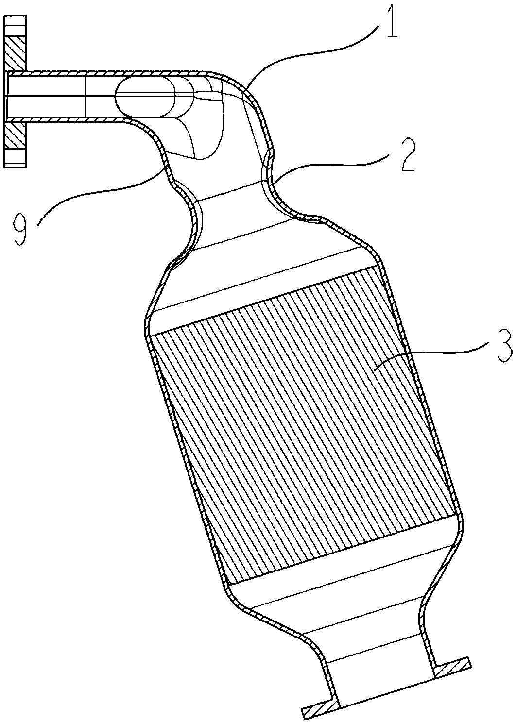
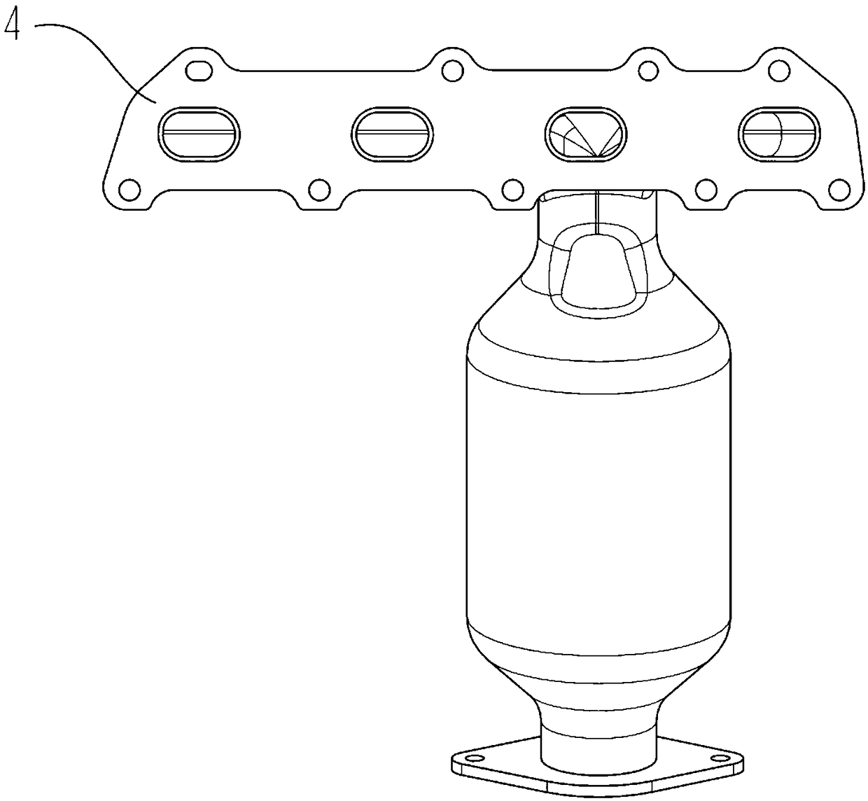
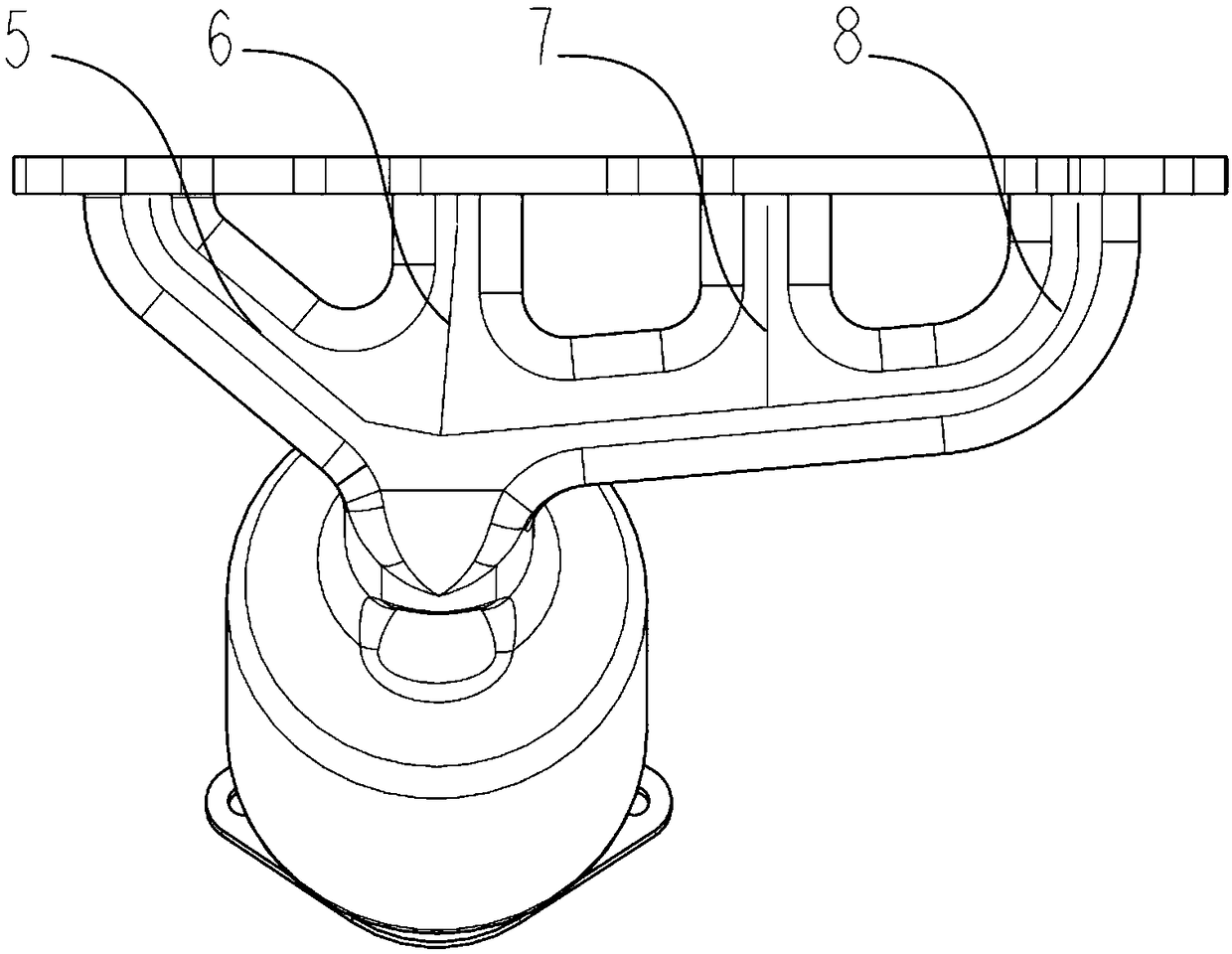
[0027] The diameter of the semicircular arc of the waist circle of the radial section of the first exhaust manifold, the second exhaust manifold, the third exhaust manifold and the fourth exhaust manifold is 19mm, and the waist circle connecting two The length of the two parallel lines at the ends of the semicircle is 31mm, the angle between the centerline of the first exhaust manifold inlet 5 and the centerline of the second exhaust manifold inlet 6 is 55°, the third row The included angle between the centerline of the gas manifold inlet 7 and the centerline of the fourth exhaust pipe inlet 8 is 85°, and the height of the raised structure 2 along the axial direction of the exhaust manifold inlet connecting transition section 9 is 40 mm. The structure 2 has a radial width of 31mm along the inlet of the exhaust manifold connecting the transition section 9, and the diameter of the catalytic converter carrier 3 is 115mm. This embodiment has been verified by experiments. Compared ...

Embodiment 2

[0029] The diameter of the semicircular arc of the waist circle of the radial section of the first exhaust manifold, the second exhaust manifold, the third exhaust manifold and the fourth exhaust manifold is 16mm, and the waist circle connects two The length of the two parallel lines at the ends of the semicircle is 29mm, the angle between the centerline of the first exhaust manifold inlet 5 and the centerline of the second exhaust manifold inlet 6 is 52°, the third row The included angle between the centerline of the gas manifold inlet 7 and the centerline of the fourth exhaust manifold inlet 8 is 82°, and the height of the raised structure 2 along the axial direction of the transition section 9 connected to the inlet of the exhaust manifold is 39mm. The radial width of the starting structure 2 along the inlet of the exhaust manifold connecting the transition section 9 is 29 mm, and the diameter of the catalytic converter carrier 3 is 112 mm. This embodiment has been verified...


PUM


Abstract

The invention provides an exhaust manifold structure for improving engine cold start emission. An exhaust main pipe is formed by four exhaust manifolds arranged at intervals; inlets of the four exhaust manifolds communicate to form an exhaust main pipe inlet; a section of connection transition between the exhaust main pipe inlet and a catalyst carrier is an exhaust main pipe inlet connection transition section; the axis of the exhaust main pipe inlet connection transition section and the axis of the catalyst carrier are in a straight line; two front-and-back symmetrically arranged projection structures inwards projected along the radial direction of the exhaust main pipe inlet connection transition section are arranged on the inner wall of the exhaust main pipe inlet connection transitionsection; and the radial cross sections of the first exhaust manifold, the second exhaust manifold and the third exhaust manifold are in waist circular shapes. Through the structure, limited exhaust heat amount can be fully utilized, the disturbance energy of exhaust air can be increased, and the flow speed is improved, so that a catalyst is quickly preheated, the light-off time of the catalyst isshortened by 20 percent, and the THC emission load under the NEDC circulation condition is reduced by 30 percent.

Description

technical field [0001] The invention belongs to the field of auto parts, relates to an exhaust manifold for a gasoline engine, and specifically designs an exhaust manifold structure for improving engine cold start emission. Background technique [0002] At present, the exhaust manifold structures commonly used in gasoline engines mainly include: [0003] The exhaust manifolds for each cylinder are separate and all converge after a relatively long distance. The advantage of this structure exhaust manifold is to eliminate the exhaust interference between the cylinders of the gasoline engine, which can improve the low-speed torque performance of the gasoline engine. The disadvantage is that the exhaust gas in the cylinder needs to go through a certain distance to reach the three-way catalytic converter, which is not conducive to the gasoline engine. Rapid ignition of the catalytic converter during cold start; [0004] According to the ignition sequence of the gasoline engine,...

Claims


Application Information

Patent Timeline
Patent Type & Authority Applications(China)
IPC IPC(8): F01N13/10
CPCF01N13/10F01N2240/20F01N2470/10
Inventor 王占峰吴乃鹏张宇璠刘金玉黄平慧陈海娥杜维明
Owner CHINA FIRST AUTOMOBILE
Why Eureka
Try Eureka