Self-driven compression type large temperature difference heat exchange unit

A heat exchange unit and compression technology, applied in the field of heating, can solve the problems of difficult installation, difficult implementation, poor economy, etc., and achieve the effects of small equipment volume, improved conveying efficiency, and high working pressure

Inactive Publication Date: 2019-02-01
赖中练
View PDF7 Cites 1 Cited by
  • Summary
  • Abstract
  • Description
  • Claims
  • Application Information

AI Technical Summary

Problems solved by technology

At present, electric-driven heat pump units can be used to reduce the return water temperature of the primary network to below 30°C, but additional power consumption is required, the economy is poor, and it is necessary to increase the power capacity of the thermal station, which is difficult to implement; hot water type lithium bromide can also be used The absorption heat pump uses high-temperature hot water as the driving force, and can also reduce the return water temperature of the primary network to below 40°C. Since the refrigerant in the lithium bromide absorption heat pump is water, it works in a near-vacuum environment, and the low water vapor density causes the equipment to Large size, high cost, difficult installation

Method used


Image

  • Self-driven compression type large temperature difference heat exchange unit
  • Self-driven compression type large temperature difference heat exchange unit
  • Self-driven compression type large temperature difference heat exchange unit

Examples


example 1

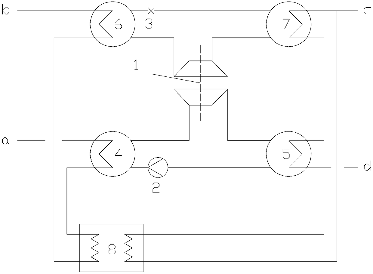
[0020] refer to figure 1 , The self-driven compression large temperature difference heat exchange unit includes a high-temperature evaporator 4, an expansion compressor 1, a high-temperature condenser 5, a working medium pump 2, a low-temperature evaporator 6, a low-temperature condenser 7, a throttle valve 3 and connecting pipelines. The primary hot water flows through the high-temperature evaporator 4, heat exchanger 8 and low-temperature evaporator 6 in turn. The primary hot water heats the working medium in the high-temperature evaporator to generate high-pressure steam. The high-pressure steam drives the expander to do work and then enters the condenser 5 for condensation. It is a liquid working fluid and releases heat to the secondary side. The condensed working fluid enters the high-temperature evaporator 4 through the working fluid pump 2; the cooled primary network hot water heats the working fluid in the low-temperature evaporator to generate low-pressure steam, which...

example 2

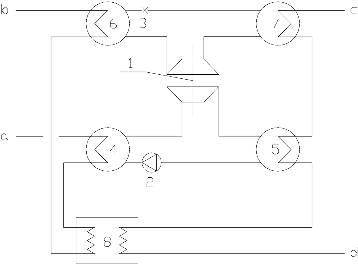
[0023] refer to figure 2 , the process on the working fluid side is the same as in Example 1, and will not be described again.

[0024] In this example, the hot water on the primary side enters the high temperature evaporator 4 , the heat exchanger 8 , and the low temperature evaporator 6 in sequence; the hot water on the secondary side enters the low temperature condenser 7 , the high temperature condenser 5 , and the heat exchanger 8 in sequence.

example 3

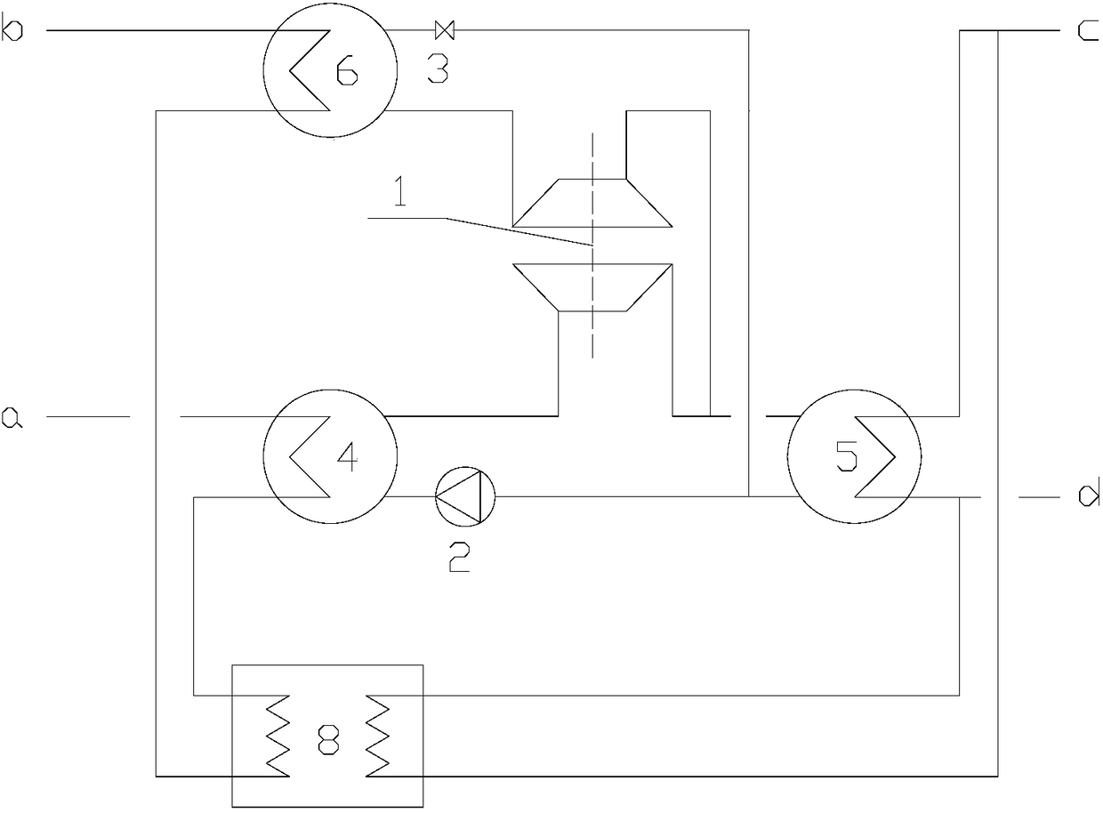
[0026] refer to image 3 , The self-driven compression large temperature difference heat exchange unit includes a high-temperature evaporator 4, an expansion compressor 1, a condenser 5, a working medium pump 2, a low-temperature evaporator 6, a throttle valve 3 and connecting pipelines. The hot water in the primary network flows through the high-temperature evaporator 4, heat exchanger 8 and low-temperature evaporator 6 in sequence. The hot water in the primary network heats the working fluid in the high-temperature evaporator to generate high-pressure steam, which drives the expander to do work and then enters the condenser 5 for condensation. It is a liquid working fluid and releases heat to the secondary side. The condensed working fluid enters the high-temperature evaporator 4 through the working fluid pump 2; the cooled primary network hot water heats the working fluid in the low-temperature evaporator to generate low-pressure steam, which is After compression, the compr...


PUM


Abstract

The invention belongs to the technical field of heating, and particularly relates to a self-driven compression type large temperature difference heat exchange unit. The heat exchange unit comprises asteam expansion circulation system, a steam compression circulation system and a heat exchanger, wherein the steam expansion circulation system comprises a high-temperature evaporator, an expander, acondenser and a working medium pump which are sequentially connected end to end; the steam compression circulation system comprises a low-temperature evaporator, a compressor, a condenser and a throttle valve which are sequentially connected end to end; the expander is connected to the compressor; primary network hot water flow in through the high-temperature evaporator, passes through the heat exchanger and then flows out from the low-temperature evaporator; and the flow path of secondary side hot water is any one or a combination of the following modes that secondary side hot water flows inthrough the heat exchanger and flows out of the condenser, or secondary side hot water flows in through the heat exchanger and flows out of the heat exchanger, or secondary side hot water flows in through the condenser and flows out of the condenser. The outlet temperature of the primary side can be lowered to be lower than the inlet temperature of the secondary side, extracted heat is conveyed tothe secondary side, the temperature difference of the primary side supply and return water is increased, the conveying efficiency is improved, and the conveying radius is increased.

Description

technical field [0001] The invention belongs to the technical field of heating, in particular to a self-driven compression heat exchange unit with large temperature difference. Background technique [0002] In central heating systems, plate heat exchangers and shell-and-tube heat exchangers are usually used to exchange heat from the primary side to the secondary side. The temperature difference between the primary side and the secondary side is the driving force for heat exchange. After heat exchange, the primary The return water temperature on the primary side cannot be lower than the inlet temperature on the secondary side, that is, the conventional heat exchange technology limits the return water temperature on the primary side to a lower limit. With the expansion of the city, the heating radius increases. In order to improve the transportation capacity, the only way to increase the water supply temperature at the primary side is to increase the water supply temperature a...

Claims


Application Information

Patent Timeline
Patent Type & Authority Applications(China)
IPC IPC(8): F24D3/10F24D3/02F24D3/18
CPCF24D3/02F24D3/10F24D3/18F24D2200/123F24D2220/06
Inventor 赖中练
Owner 赖中练
Why Eureka
Try Eureka