
Testing method for glass deflection

A test method and deflection measurement technology, which is applied in the direction of elasticity test, machine/structural component test, measuring device, etc., can solve the problem of inability to measure glass deflection, etc., and achieve the effect of strong practicability and simple operation

Inactive Publication Date: 2019-02-01
ANHUI HUAGUANG PHOTOELECTRIC MATERIAL TECH GRP CO LTD
View PDF0 Cites 0 Cited by
  • Summary
  • Abstract
  • Description
  • Claims
  • Application Information

AI Technical Summary

Problems solved by technology

When the glass thickness is 2-4mm, there will be a large error when using the method in the prior art to measure the glass deflection value. When the glass thickness is below 2mm, the method in the prior art cannot be used to measure the glass deflection.

Method used

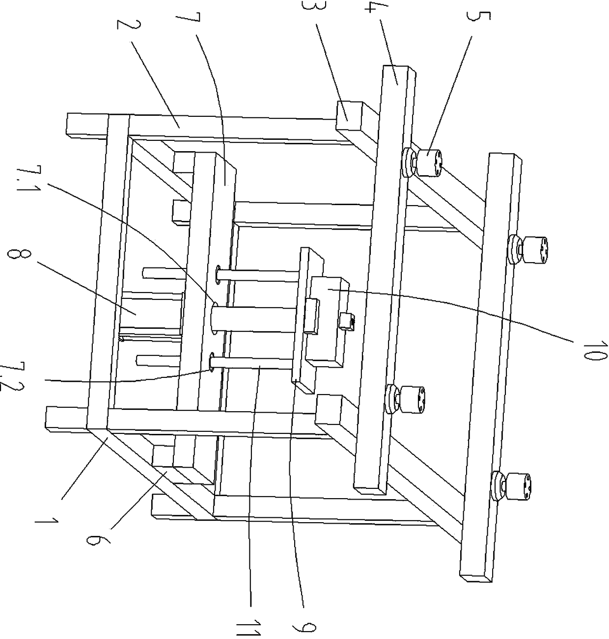

Image

  • Testing method for glass deflection
  • Testing method for glass deflection

Examples


Embodiment 1

[0025] A method for testing the deflection of float glass, comprising the following steps:

[0026] Step 1. Cutting pattern: Select a 1.7mm thick float glass plate to be tested, and cut the float glass plate to be tested into a rectangular glass pattern of 1000mm×600mm.

[0027] Step 2, pattern mark: mark the center point of the tin liquid surface and the center point of the air surface of the glass pattern. The mark is an opaque circular coating with a diameter of 3mm uniformly applied by a red oily marker. During the coating process, it must be applied evenly, and there must be no leakage of coating, so as to avoid the problem of inaccurate data caused by the transmission of infrared rays through the glass.

[0028] Step 3, zeroing the deflection measuring device: use a plate without deflection to zero the deflection rangefinder in the deflection measuring device.

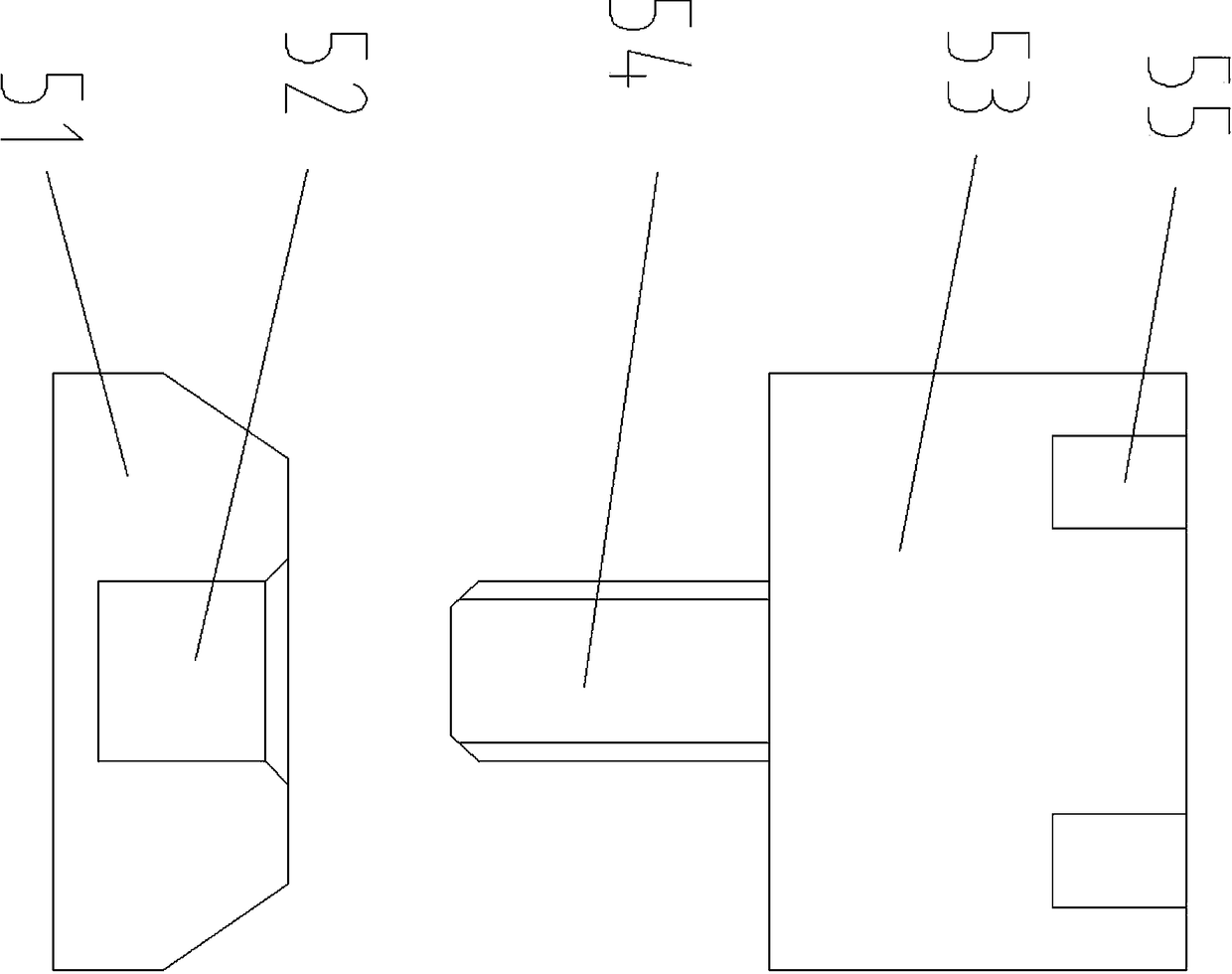
[0029] Among them, such as figure 1 and figure 2 As shown, the deflection measuring device includes a fram...

Embodiment 2

[0040] A method for testing the deflection of float glass, comprising the following steps:

[0041] Step 1. Cutting pattern: Select a 2.5mm thick float glass plate to be tested, and cut the float glass plate to be tested into a circular glass pattern with a specification of φ800mm.

[0042]Step 2. Pattern mark: Label paper is attached to the center point of the tin liquid surface and the center point of the air surface of the glass pattern, and the label paper corresponding to the center point of the tin liquid surface and the center point of the air surface of the glass pattern is used Paint a circle with a diameter of 3mm with a red marker. During the coating process, it must be applied evenly, and there must be no leakage of coating, so as to avoid the problem of inaccurate data caused by the transmission of infrared rays through the glass.

[0043] Step 3, zeroing the deflection measuring device: use a plate without deflection to zero the deflection rangefinder in the def...


PUM

PropertyMeasurementUnit
Thicknessaaaaaaaaaa
Diameteraaaaaaaaaa

Abstract

The invention discloses a testing method for glass deflection, which comprises the following steps of: step 1, cutting a pattern; step 2, marking the pattern; step 3, leveling a deflection measuring device; step 4, performing deflection testing on the pattern; and step 5, calculating the deflection value of the pattern. The invention further discloses a testing method for a flat glass. The invention has the following advantages: the method is simple to operate and high in practicability, and can measure the glass deflection of 2mm or below, thereby making up for the blank of measuring the glass deflection by the float lines in China, and guiding the tin bath and annealing production of the float glass industry in China, laying a solid foundation for producing a high-quality float glass, and playing a good role in promoting the float glass into the solar photovoltaic industry; so that the historical breakthrough in the base materials of the thin film solar cell modules in China is realized, and a solid step is taken for the photovoltaic cell module technology in China to enter the world-class.

Description

technical field [0001] The invention relates to the technical field of glass detection, in particular to a method for testing glass deflection. Background technique [0002] In the existing float glass production industry in China, by testing the deflection of the glass, it is possible to grasp the stress on the upper and lower surfaces of the glass and the impact of tin infiltration on the subsequent processing of the glass as a solar photovoltaic substrate, and reasonably adjust the tin bath and annealing process system to ensure that the glass is well-plated. The "copper indium gallium selenide" process will not be irreversibly deformed by high temperature. Float glass is used as copper indium gallium selenide substrate glass. During the selenization heat treatment process, a glass is placed in the selenization furnace at the same time. The gap between two adjacent glasses is 5mm. If the deflection value is large, the heat treatment process Large deformation will occur i...

Claims


Application Information

Patent Timeline
IPC IPC(8): G01M5/00
CPCG01M5/0075
Inventor 夏宁俞家红孙娜丽吕思稳王勇李宇王磊沈永乐
Owner ANHUI HUAGUANG PHOTOELECTRIC MATERIAL TECH GRP CO LTD
Learn More