A dual-stator synchronous condenser with rotor energy storage and its control method

A technology of adjusting the camera and double stators, which is applied in the direction of single-net parallel feeding arrangement, etc., can solve the problems of out-of-step in power failure, damage to the torque balance relationship of the motor shaft, and out-of-step of the synchronous motor, so as to expand the application field and benefit the normal operation. The effect of stable work

Active Publication Date: 2021-09-17
HOHAI UNIV
View PDF5 Cites 0 Cited by
  • Summary
  • Abstract
  • Description
  • Claims
  • Application Information

AI Technical Summary

Problems solved by technology

The synchronous motor will appear that the rotor speed is no longer consistent with the synchronous speed of the stator's rotating magnetic field, the speed will drop, and enter the asynchronous operation state. When the speed is not reached or close to the rated speed, if the excitation is switched on, it is likely to produce asynchronous phenomenon, mainly because the synchronous motor is constantly damaged by various disturbances from the power grid, load and the motor itself during the use of the motor shaft. Secondly, during the operation of the synchronous motor, if the excitation voltage is reduced or the supply voltage is reduced, so that the overload capacity of the synchronous motor, that is, the maximum output torque is less than the mechanical load torque, the synchronous motor will be out of step

Method used


Image

  • A dual-stator synchronous condenser with rotor energy storage and its control method
  • A dual-stator synchronous condenser with rotor energy storage and its control method
  • A dual-stator synchronous condenser with rotor energy storage and its control method

Examples


Embodiment Construction

[0024] The present invention will now be further described in detail in conjunction with the accompanying drawings and embodiments. These drawings are all simplified schematic diagrams, only illustrating the basic structure of the present invention in a schematic manner, so it only shows the composition related to the present invention.

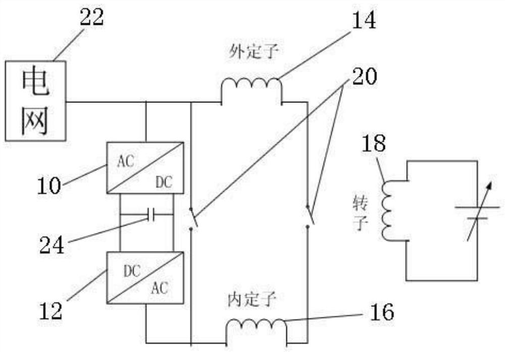
[0025] Such as figure 1 As shown, a dual-stator synchronous condenser with rotor energy storage includes power electronic equipment and a condenser. The power electronic equipment includes an AC / DC converter 10 and a DC connected to the DC side of the AC / DC converter 10. / AC converter 12, the condenser includes an outer stator 14, an inner stator 16 and a rotor 18, between one end of the outer stator 14 and one end of the inner stator 16, between the other end of the outer stator 14 and the other end of the inner stator 16 Both are connected with a switch 20 , one end of the outer stator 14 and the AC side of the AC / DC converter 10 are connec...


PUM


Abstract

The invention relates to a dual-stator synchronous condenser with rotor energy storage, including power electronic equipment and the condenser, the power electronic equipment includes an AC / DC converter, and a DC / AC converter connected to the DC side of the AC / DC converter. The converter and the condenser include a stator and a rotor. The stator includes an outer stator and an inner stator. A switch is connected between one end of the outer stator and one end of the inner stator, and between the other end of the outer stator and the other end of the inner stator. One end of the stator and the AC side of the AC / DC converter are connected to the grid, and one end of the inner stator is connected to the AC side of the DC / AC converter. The invention also relates to a control method of a double-stator synchronous condenser with rotor energy storage. The invention does not affect the conventional reactive power compensation function of the condenser itself, and the normal operation, the external stator connected to the power grid is kept in sync with the power grid, under the condition of constant 50Hz, it can also perform active power compensation to the power grid, expanding the scope of the power conditioner It is beneficial to the normal and stable work of the condenser in the power grid.

Description

technical field [0001] The invention relates to the field of stable operation of electric power systems, in particular to a double-stator synchronous condenser with rotor energy storage and a control method thereof. Background technique [0002] A synchronous motor is an AC motor that needs to keep the rotor speed and the stator's rotating magnetic field at the same speed. In terms of physical structure, the stator and rotor of the generator are two completely independent and non-interfering individuals. The stator of the generator is an active source , to generate induced electromotive force, the rotor of the generator is a reactive power source, and the winding introduces direct current from the outside to establish a magnetic field. Under the drag of the prime mover, the voltage is established and the reactive power of the alternating current is transmitted outward. From the perspective of electromagnetic principles, the two are closely related. In connection, the active ...

Claims


Application Information

Patent Timeline
Patent Type & Authority Patents(China)
IPC IPC(8): H02J3/50H02J3/48H02J3/42
CPCH02J3/42H02J3/48H02J3/50
Inventor 金哲倩陈谦鞠平周聪周文海邓晓璐金宇清秦川孙黎霞
Owner HOHAI UNIV
Why Eureka
Try Eureka