Rope-laying mechanical arm used for straw plate production system

A production system and robotic arm technology, which is applied to manipulators, program-controlled manipulators, chucks, etc., can solve problems such as affecting the efficiency of production lines and reducing product economic benefits, and achieve the effects of simple structure, improved economic benefits, and convenient operation.

Inactive Publication Date: 2019-02-05
常迪
View PDF8 Cites 2 Cited by
  • Summary
  • Abstract
  • Description
  • Claims
  • Application Information

AI Technical Summary

Problems solved by technology

[0003] In order to solve the problem that in the production process of the existing straw plate production system, manual laying of plate wires is used, which seriously affects the efficiency of the overall production line and reduces the economic benefits of the product, and further proposes a wire laying machine for the straw plate production system arm

Method used


Image

  • Rope-laying mechanical arm used for straw plate production system
  • Rope-laying mechanical arm used for straw plate production system
  • Rope-laying mechanical arm used for straw plate production system

Examples


specific Embodiment approach 1

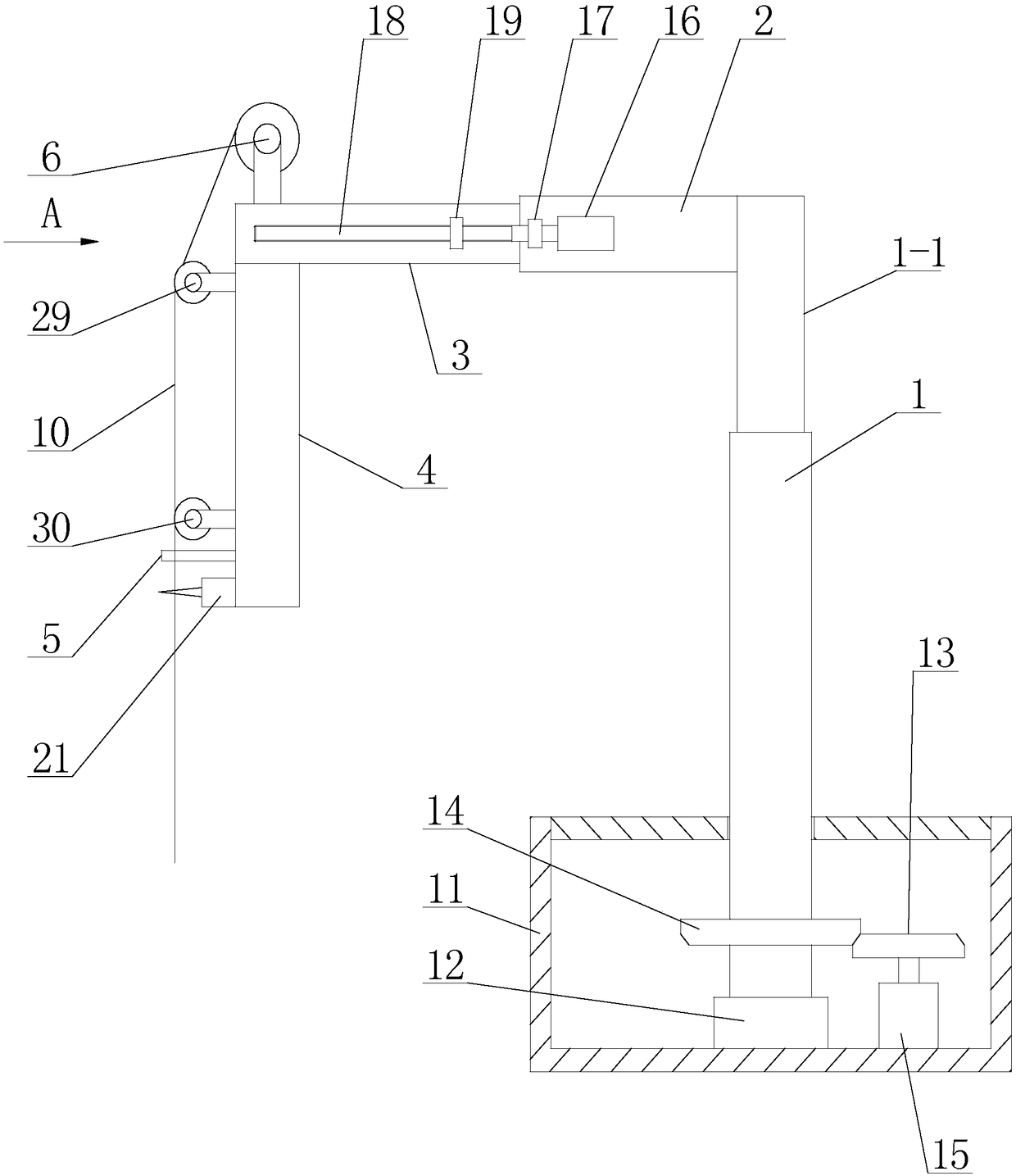
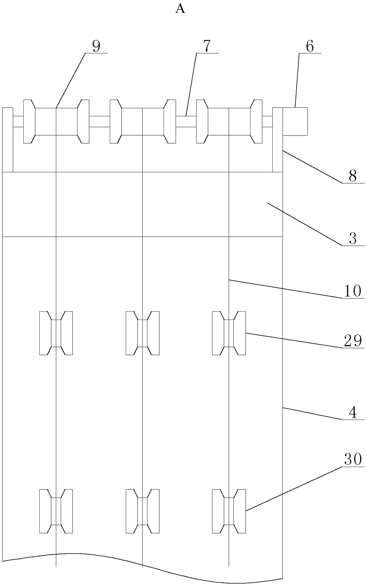
[0013] Specific implementation mode one: combine Figure 1 to Figure 3 To illustrate this embodiment, a line-laying robotic arm for a straw slab production system described in this embodiment includes a rotating base assembly, a lifting electric hydraulic cylinder 1, a fixed beam 2, a telescopic beam 3, a vertical boom 4, a translation drive mechanism, Counter 5, wire rope retractable motor 6, reel shaft 7, reel support 8, wire rope cutting mechanism and three reels 9, the lower end of lifting electric hydraulic cylinder 1 is installed on the rotating base assembly, and the fixed beam 2. Set horizontally. One end of the fixed beam 2 is fixedly connected to the upper end of the piston rod 1-1 of the lifting electric hydraulic cylinder 1. The telescopic beam 3 is set horizontally. One end of the telescopic beam 3 is installed in the other end of the fixed beam 3. The translation drive mechanism is installed on the fixed beam 2, the side wall of the telescopic beam 3 is connected...

specific Embodiment approach 2

[0014] Specific implementation mode two: combination Figure 1 to Figure 3 To illustrate this embodiment, the rotating base assembly of a line-laying robotic arm for a straw slab production system described in this embodiment includes a housing 11, a bearing seat 12, a driving gear 13, a driven gear 14, and a rotating drive motor 15, and the bearing seat 12 is fixedly installed on the bottom of the housing 11, the bottom of the lifting electric hydraulic cylinder 1 is connected to the bearing seat 12 in rotation, the rotating drive motor 15 is fixedly installed in the housing 11, and the driving gear 13 is set on the rotating shaft of the rotating driving motor 15 , the driven gear 14 is sleeved on the bottom of the lifting electric hydraulic cylinder 1, and the driving gear 13 meshes with the driven gear 14. The rotation driving motor 15 drives the driving gear 13 to rotate, and the driving gear 13 drives the bottom of the lifting electric hydraulic cylinder 1 to rotate throu...

specific Embodiment approach 3

[0015] Specific implementation mode three: combination Figure 1 to Figure 3 Describe this embodiment, the translation drive mechanism of a line-laying robotic arm for a straw slab production system described in this embodiment includes a translation drive motor 16, a reducer 17, a screw 18 and a nut 19, and the translation drive motor 16 is fixedly installed on a fixed beam On the side of 2, screw rod 18 is arranged horizontally, and one end of screw rod 18 is connected with the rotating shaft of translation drive motor 16 through reducer 17, and nut 19 is fixedly installed on the side of telescopic beam 3, and nut 19 is sleeved on the screw rod 18. The translation drive motor 16 drives the screw rod 18 to rotate forward or reverse through the reducer 17, and the screw rod 18 and the nut 19 cooperate to realize the linear reciprocating telescopic movement of the telescopic beam 3 along the fixed beam 2 . Other components and connections are the same as those in the first embo...


PUM


Abstract

The invention relates to a rope-laying mechanical arm, in particular to a rope-laying mechanical arm used for a straw plate production system, and belongs to the field of agricultural machines. By adoption of the rope-laying mechanical arm used for the straw plate production system, the problems that when an existing straw plate production system is used for production, plate ropes are laid manually, and consequentially, the efficiency of a whole production line is affected, and the economic benefits of products are reduced are solved. The rope-laying mechanical arm used for the straw plate production system comprises a rotary base assembly, an electric lifting hydraulic cylinder, a fixing beam, a telescopic beam, a vertical lazy arm, a horizontal movement driving mechanism, a counter, a rope taking-up and paying-off motor, a winding drum shaft, a winding drum support, a rope shearing mechanism and three winding drums. The lower end of the electric lifting hydraulic cylinder is mountedon the rotary base assembly. The fixing beam is horizontally arranged. One end of the fixing beam is fixedly connected with the upper end of a piston rod of the electric lifting hydraulic cylinder. The telescopic beam is horizontally arranged. One end of the telescopic arm is fixed in the other end of the fixing beam. The horizontal movement driving mechanism is mounted on the fixing beam.

Description

technical field [0001] The invention relates to a wire-laying mechanical arm, in particular to a wire-laying mechanical arm for a straw slab production system, which belongs to the field of agricultural machinery. Background technique [0002] Straw is the general term for the stem and leaf parts of mature crops, and usually refers to the remaining parts of wheat, rice, corn, potato, rapeseed, cotton, sugar cane and other crops after harvesting seeds. More than half of the photosynthetic products of crops exist in straw, which is rich in nitrogen, phosphorus, potassium, calcium, magnesium and organic matter, and is a multi-purpose renewable biological resource. Straw is also a kind of roughage, which is characterized by high crude fiber content and lignin. Although lignocellulose cannot be used by pigs and chickens, it can be absorbed and utilized by ruminants such as cattle and sheep. Although straw has many advantages, because people pay less attention to it and the resea...

Claims


Application Information

Patent Timeline
IPC IPC(8): B25J9/04B25J9/10B25J15/00
CPCB25J9/041B25J9/102B25J15/0019
Inventor 常迪赵晨希高锐李赞李云祥
Owner 常迪
Why Eureka
Try Eureka