Formant-Free Isolation Buffer

A shock absorber and non-resonance technology, which is applied in the direction of shock absorber, liquid shock absorber, shock absorber-spring combination, etc., can solve the vibration isolation buffer that is not at the midpoint of the spring piece, the friction force is uncontrollable, and there is no resonance peak Stuck and other problems, to achieve the effect of reducing the frequency of use, prolonging the life, and good vibration isolation frequency

Active Publication Date: 2020-11-17
武汉辰羽科技有限公司
View PDF5 Cites 0 Cited by
  • Summary
  • Abstract
  • Description
  • Claims
  • Application Information

AI Technical Summary

Problems solved by technology

[0004] However, there are the following problems in the non-resonant peak vibration isolation buffer of this kind of spring piece: due to the use of groove processing, when the wedge-shaped surface is relatively displaced, the proportional position of the contact point between the spring piece and the vibrator in the entire spring piece Changes occur (for example, the contact point is at the midpoint of the spring sheet at the beginning, due to the displacement at the groove, the contact point is not at the midpoint of the spring sheet at the end), the entire spring sheet is compared to a straight beam, which is equivalent to a change in deflection, which will further cause The friction between the spring sheet and the vibrator changes, which may cause the non-resonant peak vibration isolation buffer to be stuck because the friction between the grooves is greater than the spring force, and it will also be accompanied by the problem of uncontrollable friction

Method used


Image

  • Formant-Free Isolation Buffer
  • Formant-Free Isolation Buffer
  • Formant-Free Isolation Buffer

Examples


Embodiment Construction

[0026] The present invention will be described in further detail below in conjunction with the accompanying drawings and embodiments.

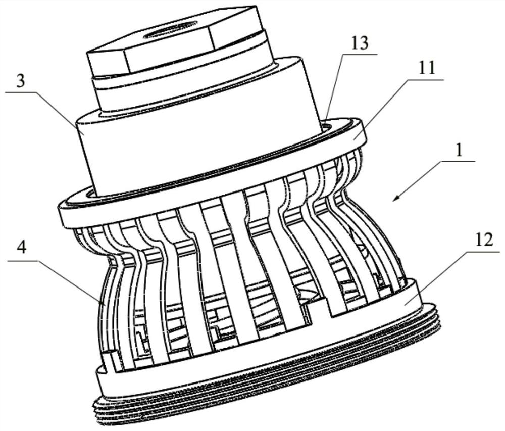
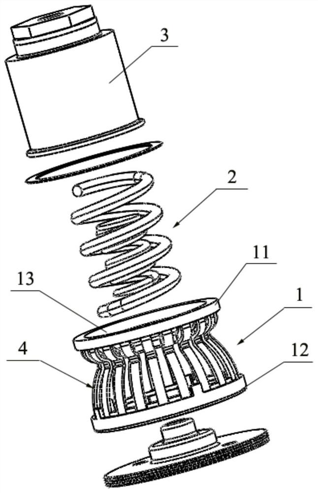
[0027] see Figure 2 to Figure 4 As shown, the embodiment of the present invention provides a vibration isolation buffer without resonance peak, which includes a connection mechanism 1 , a spring assembly 2 , a piston 3 and a damping assembly 4 .

[0028] Wherein, the connection mechanism 1 includes an upper cover plate 11 and an installation base 12 arranged at intervals, and the upper cover plate 11 is provided with a through hole 13 .

[0029] The spring assembly 2 is fixed on the installation base 12 .

[0030] One end of the piston 3 abuts against the spring assembly 2 , and the other end passes through the through hole 13 .

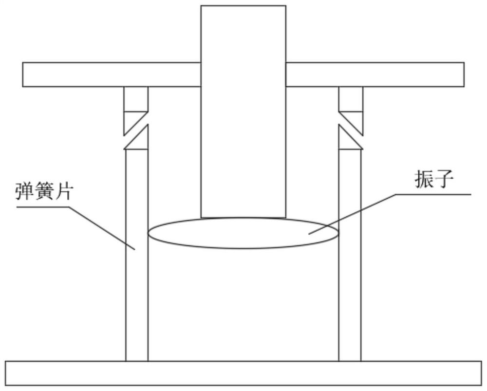
[0031] The damping assembly 4 includes a plurality of friction plates 41 arranged around the piston 3, each of the friction plates 41 includes a first arc segment 42, a second arc segment 43 and a transition segme...


PUM


Abstract

The invention discloses a vibration isolating buffer without harmonic peaks, and relates to the technical field of vibration isolator buffering devices. The vibration isolating buffer without harmonicpeaks comprises a connecting mechanism, a spring assembly, a piston and a damping assembly. The connecting mechanism comprises an upper cover plate and an installing base which are oppositely arranged in a spaced manner, and the upper cover plate is provided with a through hole. The spring assembly is fixed to the installing base. One end of the piston abuts against the spring assembly, and the other end of the piston penetrates through the through hole. The damping assembly comprises a plurality of friction plates surrounding the piston. Each friction plate comprises a first arc section, a second arc section and a transition section, wherein one end of the first arc section is connected with the transition section, the other end of the first arc section is arranged on the upper cover plate, one end of the second arc section is connected with the transition section, the other end of the second arc section is fixed to the installing base, and the transition section protrudes towards the piston and abuts against the outer wall of the piston. The vibration isolating buffer without harmonic peaks can be prevented from being stuck in the usage process, and friction force is controllable.

Description

technical field [0001] The invention relates to the technical field of vibration isolator buffer devices, in particular to a vibration isolation buffer without a resonance peak. Background technique [0002] No resonance peak vibration isolation buffer can effectively suppress resonance, realize no amplification in the resonance area, and can effectively prevent electronic equipment from being damaged in the resonance area in time, causing the performance of electronic equipment to decline or even fail. It has a stable and reliable anti-strong shock vibration isolator It can effectively avoid damage to electronic equipment caused by the shock environment. [0003] see figure 1 As shown, the existing non-resonant peak vibration isolation buffer usually adopts a spring leaf fixed at one end and simply supported at the other end, and then adopts a groove at the simply supported end, and adjusts the spring leaf by adjusting the vertical movement of the groove The friction forc...

Claims


Application Information

Patent Timeline
Patent Type & Authority Patents(China)
IPC IPC(8): F16F13/06F16F9/19F16F9/32
CPCF16F9/19F16F9/3207F16F13/06
Inventor 刘继烈熊四伍安娜
Owner 武汉辰羽科技有限公司
Why Eureka
Try Eureka