Microstrip vertical loop antenna

A loop antenna and microstrip feeder technology, applied in the field of microwave antennas, can solve problems such as complex design, and achieve low cost, small size, and simple design and production

Active Publication Date: 2019-02-05
NANJING UNIV OF SCI & TECH
View PDF8 Cites 1 Cited by
  • Summary
  • Abstract
  • Description
  • Claims
  • Application Information

AI Technical Summary

Problems solved by technology

[0002] In the ground-to-ground missile antenna, because it has a funnel-shaped beam requirement for the antenna beam, the missile antenna often needs to be conformal on the missile body, resulting in a complex design

Method used


Image

  • Microstrip vertical loop antenna
  • Microstrip vertical loop antenna
  • Microstrip vertical loop antenna

Examples


Embodiment

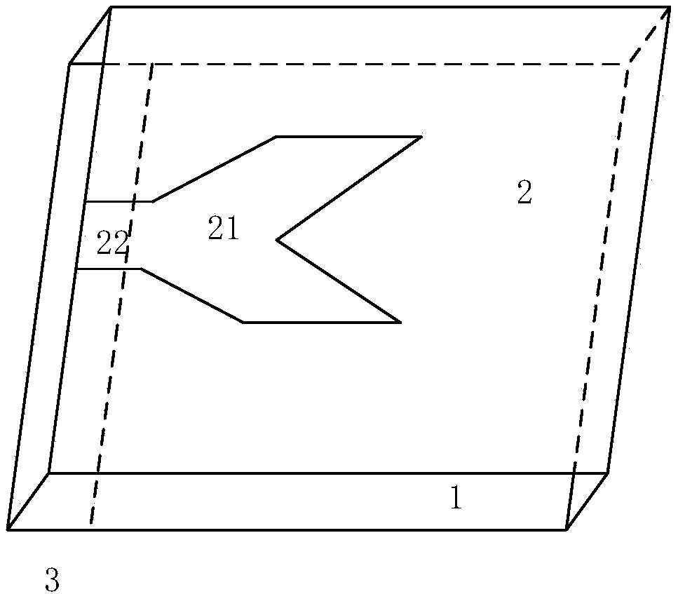
[0019] Such as figure 1 , 2 As shown, a microstrip vertical loop antenna includes a rectangular dielectric substrate 1, an antenna patch layer 2 attached to the upper surface of the dielectric substrate 1, and a metal ground layer 3 attached to the lower surface of the dielectric substrate 1. The antenna patch Layer 2 includes a radiation patch 21 and a microstrip feeder 22 ; the radiation patch 21 is connected to the microstrip feeder 22 .

[0020] combine figure 1 , Part 1 in the figure is the dielectric substrate of the antenna, its thickness is 1mm, and its relative permittivity is 2.52; Part 2 in the figure is the patch layer of the antenna; Part 3 in the figure is the metal ground layer.

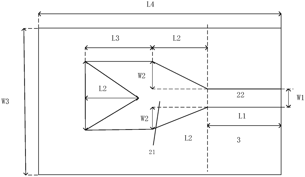
[0021] combine figure 2 , the length L1 of the microstrip feeder 22 is 3 mm, the width W1 is 0.6 mm, the metal ground layer is equal in width to the dielectric substrate, and the length is equal to the length of the microstrip feeder 22; the radiation patch 21 is an arrow-feather-s...


PUM

PropertyMeasurementUnit
Thicknessaaaaaaaaaa

Abstract

The invention discloses a microstrip vertical loop antenna. The antenna includes a rectangular dielectric substrate, an antenna patch layer attached to the upper surface of the dielectric substrate, and a metal ground plane attached to the lower surface of the dielectric substrate; the antenna patch layer includes a radiation patch and a microstrip feed line; the radiation patch is connected to the microstrip feed line; the metal ground plane does not completely cover the dielectric substrate, the width of the metal ground plane is same as the width of the dielectric substrate, and the lengthof the metal ground plane is equal to the length of the microstrip feed line; and the radiation patch is an arrow feather-shaped heptagon and in a axisymmetric structure, and the symmetric axis is coincident with the center line of the microstrip feed line. The antenna wave beams of the antenna are in funnel shapes, so that the antenna can be used as a missile-borne antenna.

Description

technical field [0001] The invention belongs to the technical field of microwave antennas, in particular to a microstrip vertical loop antenna with sufficiently wide bandwidth, which can meet the beam pointing requirements of missile-borne antennas. Background technique [0002] In the ground-to-ground missile missile antenna, because it has a funnel-shaped beam requirement for the antenna beam, the missile antenna often needs to be conformal on the missile body, which makes its design complicated. [0003] The microstrip antenna is on a thin dielectric substrate, one side is attached with a thin metal layer as a grounding plate, and the other side is made of a metal patch of a certain shape by photolithography and other methods. The feed constitutes the antenna. If the shape of the patch is a slender strip, it is a microstrip dipole antenna. When the patch is an area unit, it is a microstrip antenna. Microstrip antenna has the advantages of miniaturization, easy integrati...

Claims


Application Information

Patent Timeline
IPC IPC(8): H01Q1/38H01Q1/48H01Q1/50H01Q1/28
CPCH01Q1/28H01Q1/38H01Q1/48H01Q1/50
Inventor 张淑宁范利光范聿杰范婉华刘倩云王伶俐邢姣蒋旭峰陈魁宇徐焕昊
Owner NANJING UNIV OF SCI & TECH
Why Eureka
Try Eureka