Supercharge Your Innovation With Domain-Expert AI Agents!

Dispersion estimation methods and devices and optical receiver

A dispersion and estimated value technology, applied in dispersion estimation methods, optical receivers, and devices, can solve problems such as difficult to meet application scenarios, time-consuming, DSP chip algorithm failure, etc., to ensure real-time activation and recovery, and reduce computational complexity , the effect of improving the accuracy

Active Publication Date: 2019-02-05
WUHAN FISILINK MICROELECTRONICS TECH CO LTD
View PDF7 Cites 0 Cited by
  • Summary
  • Abstract
  • Description
  • Claims
  • Application Information

AI Technical Summary

Problems solved by technology

Since the chromatic dispersion (Chromatic Dispersion, CD) in the optical fiber link changes dynamically with environmental conditions such as temperature and pressure, as well as factors such as fiber length and path changes caused by the dynamic configuration of the route, when performing polarization mode dispersion on the optical signal Before compensation, carrier recovery and other transmission damage compensation, if the fiber dispersion cannot be fully compensated, there will be a large intersymbol interference (Inter Symbol Interference, ISI) in the optical signal, which will eventually lead to the failure of the entire DSP chip algorithm
During the initial deployment of communication equipment, during the initial power-on and reset of the DSP chip, or when the communication equipment is powered on again after the service interruption resumes, fast and effective estimation and compensation of chromatic dispersion is the premise to ensure the normal operation of the communication equipment and the timely opening of services. However, the existing dispersion estimation method has high computational complexity and takes a long time, which is difficult to meet the needs of these application scenarios

Method used


Image

  • Dispersion estimation methods and devices and optical receiver
  • Dispersion estimation methods and devices and optical receiver
  • Dispersion estimation methods and devices and optical receiver

Examples


Embodiment Construction

[0056] The present invention will be further described in detail below in conjunction with the accompanying drawings and specific embodiments.

[0057] An embodiment of the present invention provides a method for estimating dispersion, including:

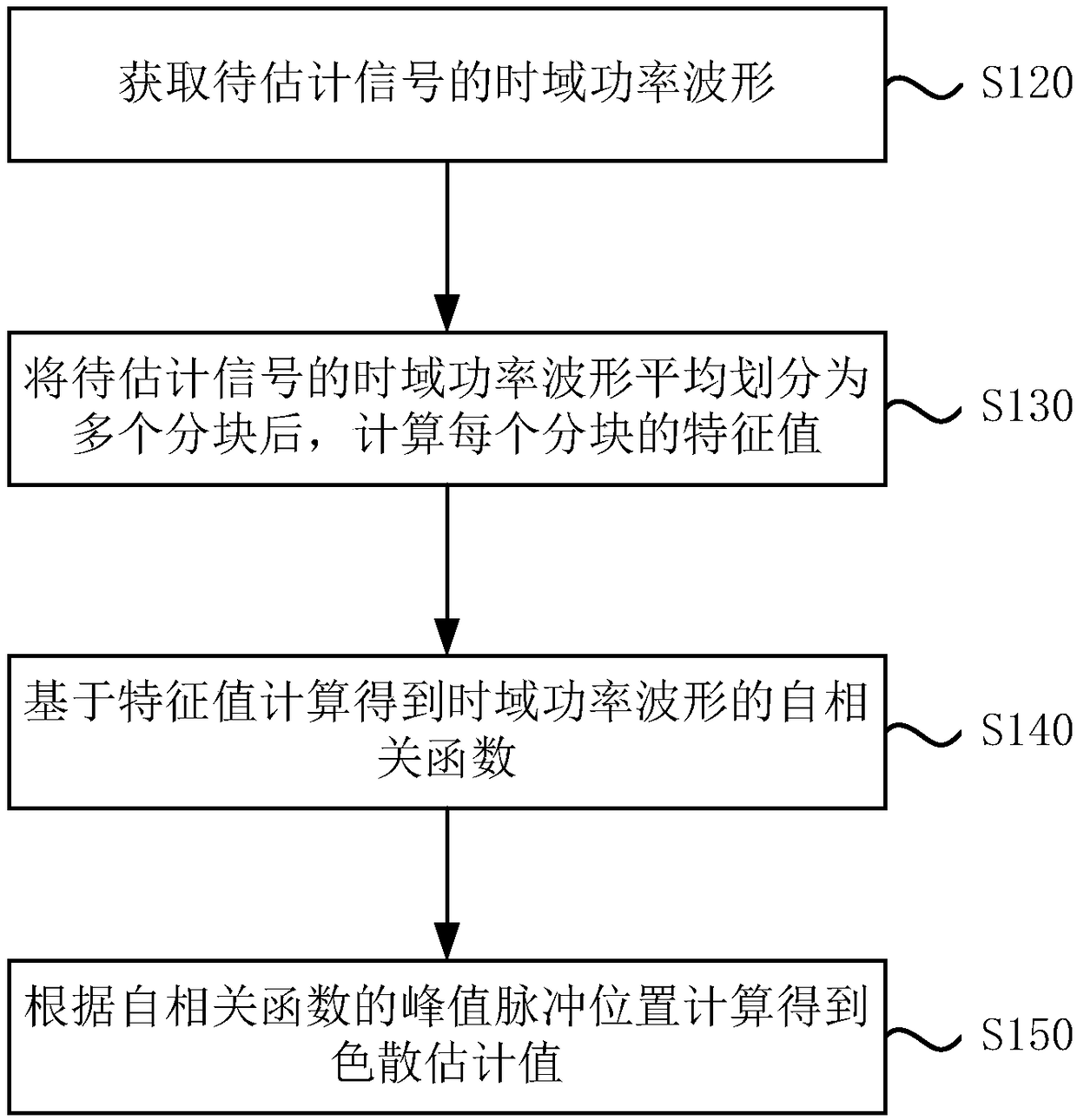
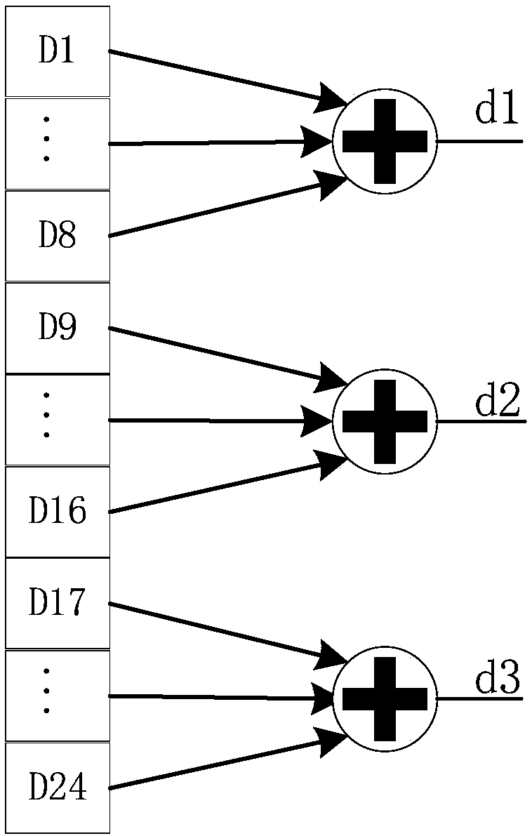
[0058] After the time-domain power waveform of the signal to be estimated is evenly divided into multiple blocks, the feature value of each block is calculated, wherein each block includes M data, and M≥2.

[0059] The autocorrelation function of the time-domain power waveform is calculated based on the eigenvalues.

[0060] The dispersion estimate is calculated from the peak pulse position of the autocorrelation function.

[0061] After the time-domain power waveform of the signal to be estimated is divided into multiple blocks, the autocorrelation function and dispersion estimation value of the time-domain power waveform are calculated according to the eigenvalues ​​of each block, which greatly reduces the computational complexit...


PUM


Abstract

The invention discloses dispersion estimation methods and devices and an optical receiver. A dispersion estimation method comprises the steps of averagely dividing a time domain power waveform of a to-be-estimated signal into a plurality of blocks, and computing an eigenvalue of each block, wherein each block comprises M pieces of data, and the M is greater than or equal to 2; carrying out computing to obtain an autocorrelation function of the time domain power waveform based on the eigenvalues; and carrying out computing to obtain a dispersion estimated value according to a peak pulse position of the autocorrelation function. According to the methods, the devices and the optical receiver, wide range rapid dispersion estimation can be realized.

Description

technical field [0001] The invention relates to the technical field of communication, in particular to a dispersion estimation method, device and optical receiver. Background technique [0002] Digital coherent optical communication technology uses coherent detection to obtain all optical field information such as the amplitude, phase, frequency, and polarization of optical signals, which can greatly improve the transmission rate and capacity of optical fiber channels, so it has been widely used in long-distance backbone 100G optical communication systems. , and will even play a more important role in single-wavelength 400G optical transmission, becoming the main development trend in the field of high-speed and large-capacity optical fiber communication in the future. Not only that, digital coherent optical communication technology is gradually penetrating into some bandwidth-intensive medium and short-distance application scenarios, such as metropolitan area networks and da...

Claims


Application Information

Patent Timeline
IPC IPC(8): H04B10/61
CPCH04B10/6161
Inventor 冯振华胡杰朱齐雄胡烽郑林
Owner WUHAN FISILINK MICROELECTRONICS TECH CO LTD
Features
  • R&D
  • Intellectual Property
  • Life Sciences
  • Materials
  • Tech Scout
  • Unparalleled Data Quality
  • Higher Quality Content
  • 60% Fewer Hallucinations
Learn More