Embedded reflective eyepiece

A technology of eyepieces and reflectors, applied in magnifying glasses, instruments, optics, etc., to achieve the effect of reducing chromatic aberration and improving the performance of eyepieces

Inactive Publication Date: 2019-02-05
KOPIN CORPORATION
View PDF5 Cites 6 Cited by
  • Summary
  • Abstract
  • Description
  • Claims
  • Application Information

AI Technical Summary

Problems solved by technology

Beamsplitter reflective coating at convex surface

Method used


Image

  • Embedded reflective eyepiece
  • Embedded reflective eyepiece
  • Embedded reflective eyepiece

Examples


Embodiment Construction

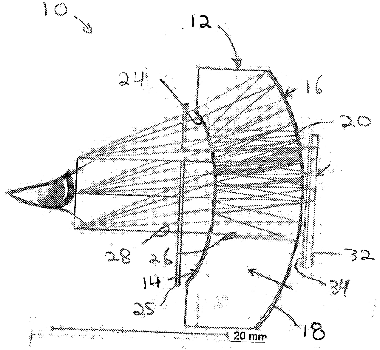
[0020] The present invention relates generally to reflective collimating eyepieces, and methods of forming magnified and collimated images. "Embedded" is a reference to the single monolithic nature of an optical design in which reflective elements are embedded or incorporated on both outer surfaces.

[0021] In one embodiment of the present invention, as figure 1 As shown, reflective collimating eyepiece 10 includes optical lens 12 . Optical lens 12 defines a concave surface 14 and a convex surface 16 opposite concave surface 14 . A beam splitter reflective coating 18 is located at the convex surface 14 . Typically, this is a dielectric coating with about a 50:50 coating performance ratio. 50:50 refers to the ratio or split ratio between reflected light and transmitted light at the beam splitter coating. Other ratios or reflective splits are also possible. The coating is designed to maintain the polarization of both transmitted and reflected polarized light. It can also ...


PUM


Abstract

An embedded reflective eyepiece includes an optical lens (12), a beam splitter and reflective coating (18) at a convex surface (16) of the optical lens and a circular polarizing reflector (24) surfacehaving a concave surface (14) of the optical lens. A method for forming a magnified image includes emitting circularly polarized light from a display source, at least partially refracting the circularly polarized light across a convex surface of a beam splitter reflective coating across a lens, at least partially reflecting refracted circularly polarized light internally off a concave circularlypolarized reflector surface of the lens, and at least partially reflecting a reflected circularly polarized light internally off of the beam splitter reflective coating at the convex surface.

Description

technical field [0001] This application claims the benefit of U.S. Provisional Application No. 62 / 289,408, filed February 1, 2016. The entire teachings of the aforementioned applications are incorporated herein by reference. Background technique [0002] While several types of optical collimation devices exist, they are all limited in collimation accuracy and often also in size and weight. Examples of known optical collimation devices include those taught in U.S. Patent No.: 3,679,290, which discloses an optical filter system using a combination of cholesteric liquid crystal films; U.S. Patent No.: 4,704,010, which discloses a An arrangement of planar convex lenses in which collimation marks are applied on the convex surface and a reflective coating is applied to the central part of the plane; and U.S. Patent No.: 5,050,966 which teaches a method by using multiple cholesteric elements tuned to different wavelengths Manufactured multi-color display system. [0003] Two oth...

Claims


Application Information

Patent Timeline
Patent Type & Authority Applications(China)
IPC IPC(8): G02B27/01G02B25/00
CPCG02B5/3016G02B5/3083G02B25/001G02B25/007G02B27/0172G02B27/027G02B27/142G02B27/286G02B27/30G02B2027/0178
Inventor T·J·爱德华兹
Owner KOPIN CORPORATION
Why Eureka
Try Eureka