Clamp for fixed-position welding of impeller

A technology of positioning welding and impeller, applied in welding equipment, auxiliary welding equipment, welding/cutting auxiliary equipment, etc., can solve the problems of no impeller welding auxiliary tools, high cost of automatic welding equipment, affecting the quality of the impeller, etc., and achieve excellent positioning effect. , Ingenious structure, good fixed effect

Inactive Publication Date: 2019-02-12
CHANGZHOU COLLEGE OF INFORMATION TECH
View PDF0 Cites 5 Cited by
  • Summary
  • Abstract
  • Description
  • Claims
  • Application Information

AI Technical Summary

Problems solved by technology

At present, the existing impeller welding methods usually use manual welding, and a small amount of automatic welding equipment is used to draw auxiliary lines on the bottom plate of the impeller, and then weld the blades to the bottom plate one by one, and finally weld the top plate to the top of the blade. The step of welding blades is extremely important. The accuracy of blade welding will aff...

Method used


Image

  • Clamp for fixed-position welding of impeller
  • Clamp for fixed-position welding of impeller
  • Clamp for fixed-position welding of impeller

Examples


Embodiment 1

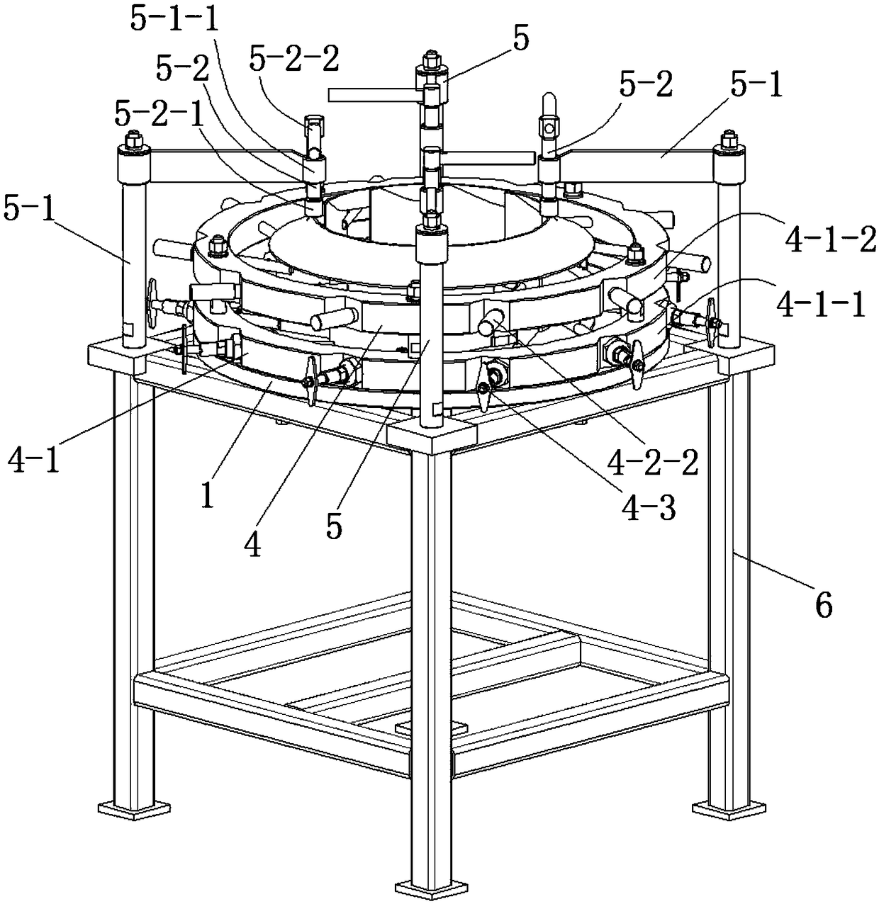
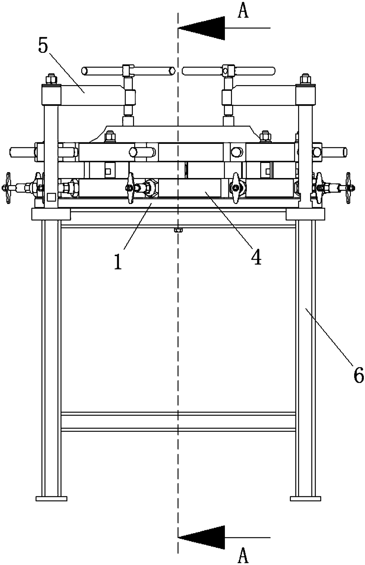
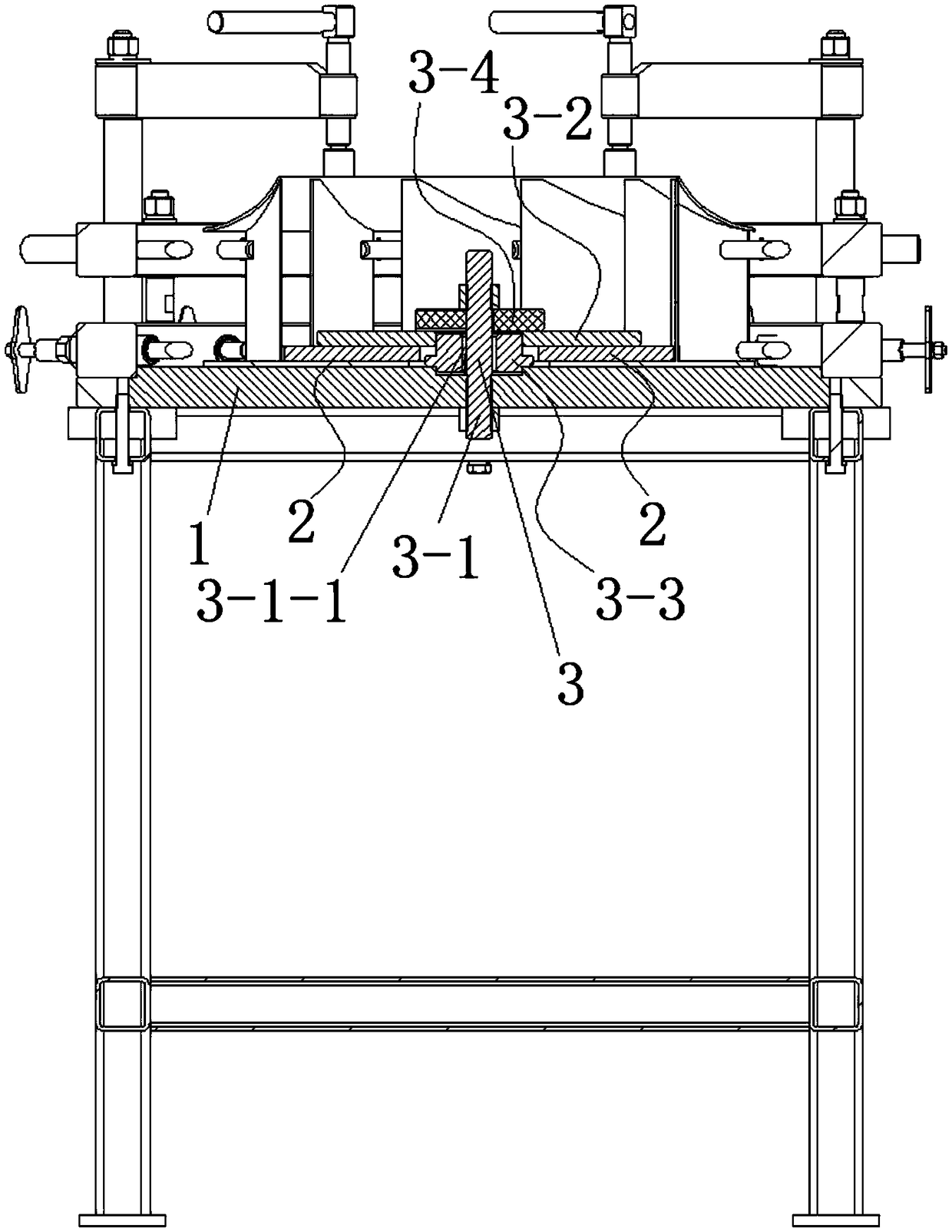
[0051] See Figure 1 to Figure 6 , the fixture for auxiliary impeller welding in this embodiment includes a base plate 1 , a positioning member 2 , a bottom plate fixing assembly 3 , a blade fixing mechanism 4 and a top plate fixing assembly 5 .

[0052] The positioning member 2 fixes the impeller bottom plate on the base plate 1 through the bottom plate fixing assembly 3 . The positioning member 2 is provided with several positioning parts for positioning the blades of the impeller. The blade fixing mechanism 4 positions each blade of the impeller. The top plate fixing assembly 5 fixes the impeller top plate on the top of the blade.

[0053] The bottom plate fixing assembly 3 includes a screw rod 3-1, a pressing plate 3-2, a fixing sleeve 3-3 and a washer 3-4. The screw rod 3 - 1 is installed on the base plate 1 . The pressing plate 3-2 is sleeved on the screw rod 3-1, and is located directly above the positioning member 2. Both the top and the bottom of the screw rod 3-...

Embodiment 2

[0075] This embodiment is basically the same as Embodiment 1, the difference is:

[0076] The positioning assembly of the blade fixing mechanism 4 includes a first positioning rod 4-2. There are two first positioning rods 4-2. One end of a first positioning rod 4-2 penetrates the side wall of the bottom frame 4-1-1 and extends into the bottom frame 4-1-1 to be positioned with the blade of the impeller, and one end of the other first positioning rod 4-2 runs through The side wall of the top frame 4-1-2 extends into the top frame 4-1-2 to be positioned with the blade of the impeller, and the two first positioning rods 4-2 are on the same vertical plane.

[0077] Preferably, one end of the first positioning rod 4-2 of the positioning assembly of the blade fixing mechanism 4 is provided with a second slot 4-2-1 matched with the blade of the impeller.

[0078] Preferably, the other end of the first positioning rod 4-2 of the positioning assembly of the blade fixing mechanism 4 is...

Embodiment 3

[0082] This embodiment is basically the same as Embodiment 1, the difference is:

[0083] The positioning assembly of the blade fixing mechanism 4 includes a second positioning rod 4-3, a fixing sleeve 4-4 and a spring. The second positioning rod 4-3, the spring and the fixed sleeve 4-4 are all provided with two.

[0084] The two fixing sleeves 4-4 are respectively fixed on the bottom frame 4-1-1 and the top frame 4-1-2, and one ends of the two fixing sleeves 4-4 pass through the bottom frame 4-1-1 and the top frame respectively. Side walls of box 4-1-2. One end of a second positioning rod 4-3 penetrates a fixing sleeve 4-4 and extends into the bottom frame 4-1-1 to be positioned with the blade of the impeller, and one end of the other second positioning rod 4-3 passes through another fixing sleeve The barrel 4-4 stretches into the top frame 4-1-2 and is positioned with the blade of the impeller. The two springs are respectively arranged in the two fixing sleeves 4-4, and t...


PUM


Abstract

The invention discloses a clamp for fixed-position welding of an impeller. The clamp comprises a substrate plate, a positioning part, a bottom plate fixing assembly, a blade fixing mechanism, top plate fixing assemblies and a rack. The positioning part fixes an impeller bottom plate to the substrate plate through the bottom plate fixing assembly; a plurality of positioning portions for positioningblades of the impeller are arranged on the positioning part; the blade fixing mechanism positions each blade of the impeller; the top plate fixing assembly fixes an impeller top plate to the top of the blade; both the substrate plate and the top plate fixing assembly are fixed to the top surface of the rack; the plurality of top plate fixing assemblies are arranged on the top of the rack and surround the positioning part; each top plate fixing assembly comprises a substrate rod and a fixed bar. The clamp is skillful in structure. The positioning portions of the positioning part position the bottoms of the blades, so that the blades are positioned to the impeller bottom plate stably. The impeller fixing mechanism enhances positioning of the blades. The top plate fixing assemblies are skillful in structure, excellent in positioning effect and simple to operate and convenient to weld the impeller. The impeller welding precision is improved greatly.

Description

technical field [0001] The invention relates to a fixture for location welding of an impeller. Background technique [0002] The impeller is an important part of the fan, and its size and precision directly affect the mechanical properties, working efficiency and service life of the pump. At present, the impellers are assembled and welded by welding the blades to the top plate and the bottom plate respectively. At present, the existing impeller welding methods usually use manual welding, and a small amount of automatic welding equipment is used to draw auxiliary lines on the bottom plate of the impeller, and then weld the blades to the bottom plate one by one, and finally weld the top plate to the top of the blade. The step of welding blades is extremely important. The accuracy of blade welding will affect the quality of the entire impeller, while the efficiency of manual blade welding is extremely low, and the welding accuracy is not high, and the defective rate is extreme...

Claims


Application Information

Patent Timeline
IPC IPC(8): B23K37/04
CPCB23K37/0443
Inventor 唐静
Owner CHANGZHOU COLLEGE OF INFORMATION TECH
Why Eureka
Try Eureka