Closed type multi-link high-speed precise punch mechanism
A precision punching and high-speed technology, which is applied in the field of mechanical pressure processing, can solve the problems of not designing the dynamic precision compensation structure of the bottom dead point and increasing the complexity of the whole machine structure, so as to realize the dynamic precision of the bottom dead point and improve the ability to resist partial load , the effect of improving the structural rigidity
- Summary
- Abstract
- Description
- Claims
- Application Information
AI Technical Summary
Problems solved by technology
Method used
Image
Examples
Embodiment 1
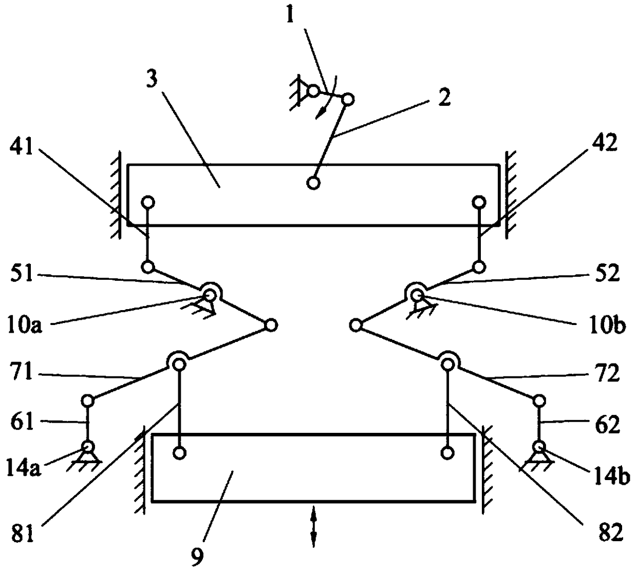
[0022] Such as figure 1 As shown, it is a structural schematic diagram of a closed multi-rod high-speed precision punch mechanism of the present invention, including a crank slider mechanism, a left branch chain, a right branch chain and a main slider 9 . The slider crank mechanism and the main slider 9 are vertically arranged on the fuselage, the slider crank mechanism is arranged directly above the fuselage, the main slider 9 is arranged directly below the fuselage, and the main slider 9 is connected to the fuselage through a moving pair. The left branch chain and the right branch chain are symmetrically connected in parallel between the slider crank mechanism and the main slider 9 .
[0023] The slider crank mechanism includes a crank 1, a connecting rod 2 and a balance slider 3. The crank 1 is connected to the fuselage through a rotating pair, the balance slider 3 is connected to the fuselage through a moving pair, and one end of the connecting rod 2 is connected to the fu...
Embodiment 2
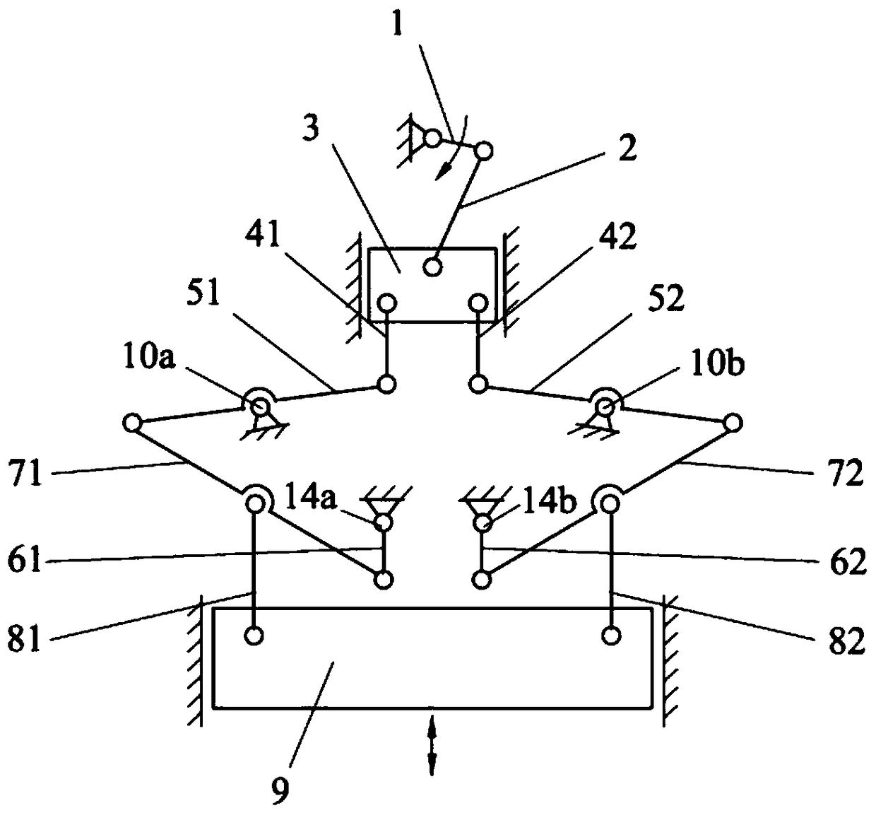
[0027] Such as figure 2As shown, the difference between this embodiment and Embodiment 1 is that the two groups of lever mechanisms of the left branch chain and the right branch chain in the main transmission system in Embodiment 1 are changed from the internal drive mode to the external drive mode. Specifically, in the vertical direction, the left swing link 41 in the left branch chain and the right swing link 42 in the right branch chain are located inside the turning pair 10a and the turning pair 10b, that is, on the right side of the turning pair 10a and the turning pair 10b on the left side. The left pull rod 61 in the left branch chain and the right pull rod 62 in the right branch chain are located inside the swivel pair 10a and the swivel pair 10b, that is, on the right side of the swivel pair 10a and the left side of the swivel pair 10b. The left push rod 81 in the left branch chain and the right push rod 82 in the right branch chain are located on the outside of the...
Embodiment 3
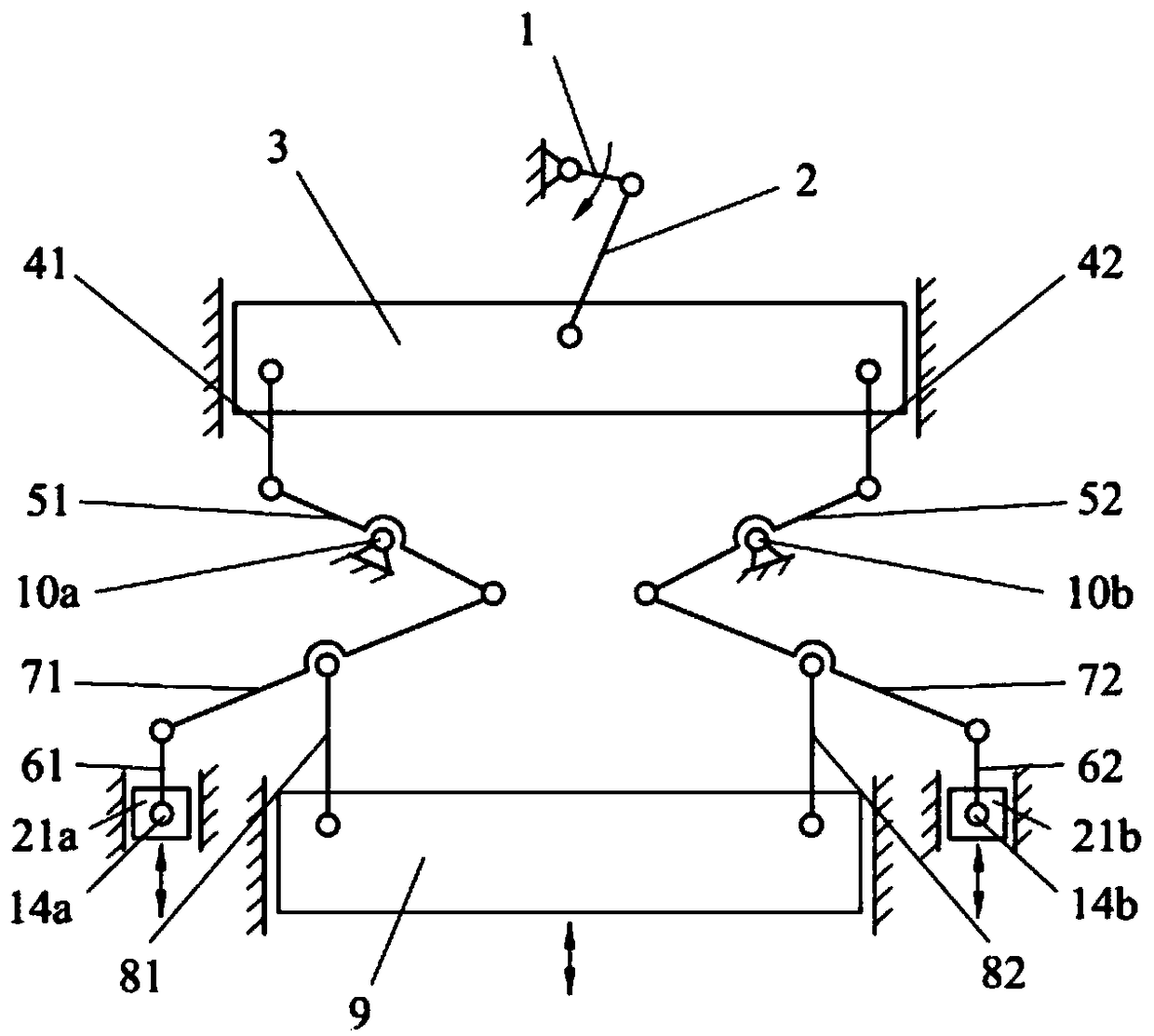
[0029] Such as image 3 As shown, the difference between this embodiment and Embodiment 1 is that an adjustment structure for dynamic precision compensation of the bottom dead center is added. One end of the left pull rod 61 in the left branch chain and one end of the right pull rod 62 in the right branch chain are respectively connected with the micro-motion adjustment slider 21a and the micro-motion adjustment slider 21b through the rotary pair 14a and the rotary pair 14b, and the left pull rod in the left branch chain The other end of the other end of 61 and the right pull rod 62 in the right side chain link to each other with the left pole 71 in the left side chain and the right pole 72 in the right side chain through a rotating pair respectively, and the fine movement adjustment slide block 21a and the fine movement adjustment slide block The block 21b is installed on the fuselage and symmetrically arranged on both sides of the fuselage, and the bottom dead center accurac...
PUM
 Abstract
Description
Claims
Application Information
 - R&D
- Intellectual Property
- Life Sciences
- Materials
- Tech Scout
- Unparalleled Data Quality
- Higher Quality Content
- 60% Fewer Hallucinations
Browse by: Latest US Patents, China's latest patents, Technical Efficacy Thesaurus, Application Domain, Technology Topic, Popular Technical Reports.
© 2025 PatSnap. All rights reserved.Legal|Privacy policy|Modern Slavery Act Transparency Statement|Sitemap|About US| Contact US: help@patsnap.com


