
Spheroidizing annealing furnace

A technology of spheroidizing annealing furnace and furnace mouth, which is applied in the direction of furnace, heat treatment furnace, furnace type, etc. It can solve the problems of different annealing degree of steel, large temperature difference between upper and lower, which affects processing and use, and achieve uniform annealing effect and temperature difference. Small, practical effect

Pending Publication Date: 2019-02-12
嘉兴中茂工业炉有限公司
View PDF0 Cites 1 Cited by
  • Summary
  • Abstract
  • Description
  • Claims
  • Application Information

AI Technical Summary

Problems solved by technology

[0002] The spheroidizing annealing furnace is used for spheroidizing annealing of steel. It mainly lays heating wires on the inner wall of the furnace, and then closes the furnace cover to increase the temperature in the furnace and last for a certain period of time to realize the spheroidizing annealing operation. However, the existing The structure of the furnace body is simple, and the temperature at different positions in the furnace is different, resulting in different annealing degrees of the steel, which affects subsequent processing and use; and the steel is placed on the bottom of the furnace for annealing, the temperature at the bottom is higher than that at the top, and the temperature difference between the upper and lower sides is large. bad

Method used


Image

  • Spheroidizing annealing furnace
  • Spheroidizing annealing furnace
  • Spheroidizing annealing furnace

Examples


Embodiment Construction

[0017] The present invention will be further described below in conjunction with the accompanying drawings and preferred embodiments.

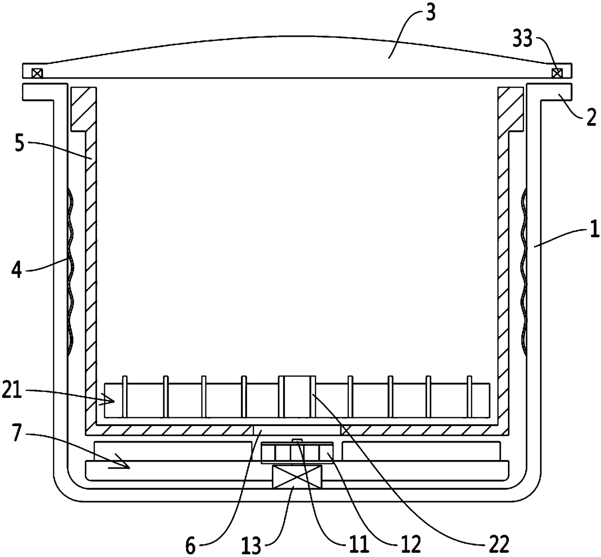
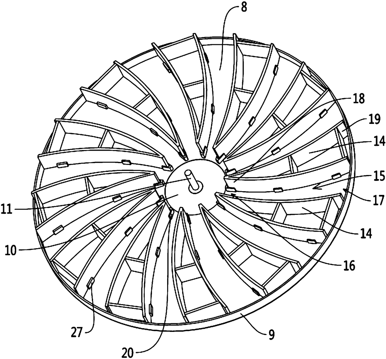
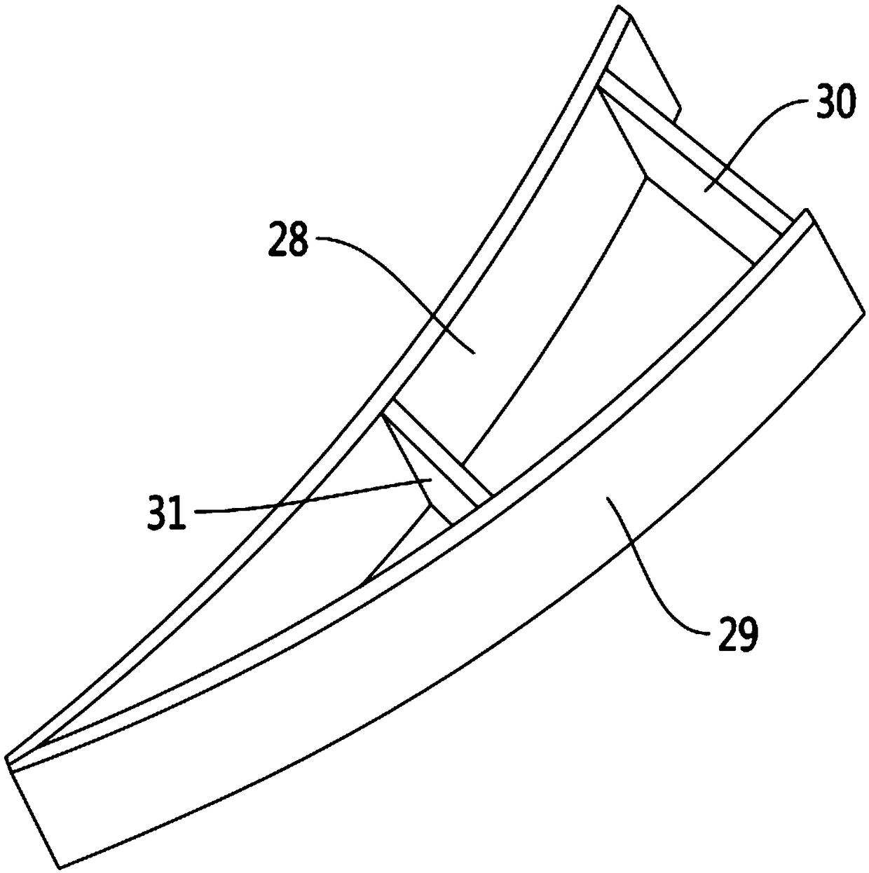
[0018] see Figures 1 to 5 As shown, a spheroidizing annealing furnace involved in this embodiment includes an outer furnace body 1 with the furnace mouth facing upwards, the outer furnace body 1 has a shoulder 2, and the outer furnace body 1 is also provided with a furnace cover 3, The inner wall of the outer furnace body 1 is provided with an electric heating wire 4, the outer furnace body 1 is provided with an inner furnace body 5, the bottom of the inner furnace body 5 has a vent 6, and the inner bottom of the outer furnace body 1 is There is a guide frame 7 located below the inner furnace body 5, the guide frame 7 includes a guide base plate 8, the edge of the guide base plate 8 has a vertically raised flange 9, and the center of the guide base plate 8 has a wind wheel installation area 10. In the center of the wind wheel installation ar...


PUM


Abstract

The invention discloses a spheroidizing annealing furnace which comprises an external furnace body. The external furnace body is provided a furnace shoulder. A furnace cover is arranged on the external furnace body. Electrical heating wires are arranged on the external furnace body. The external furnace body is provided with an internal furnace body with air openings. A stream guidance frame is arranged on the inner bottom of the external furnace body. The stream guidance frame comprises a stream guidance bottom board. A wind wheel installation area is arranged at the center of the stream guidance bottom board. A wind wheel shaft is arranged at the center of the wind wheel installation area. A wind wheel is arranged on the wind wheel shaft which is connected with a motor. Wind guide piecesare arranged on the stream guidance bottom board; a material loading plate is arranged on the internal furnace body. The material loading plate comprises a centre cylinder, extending side plates arearranged on the centre cylinder in a ring array manner. A plurality of supporting circular ring pieces are arranged at the outer side of the centre cylinder, embedding clamping grooves are arranged inthe extending side plates. The supporting circular ring pieces are embedded in the embedding clamping grooves. The spheroidizing annealing furnace has the advantages that the furnace temperature is uniform and stable and the annealing effect is even through the distribution of the internal air flow; and the rolled steel can be elevated, so that the difference between the upper and lower portion temperatures is small, and the annealing is even through the arrangement of the grating-shaped material loading plate.

Description

technical field [0001] The invention relates to the technical field of annealing furnaces, more specifically, it relates to a spheroidizing annealing furnace. Background technique [0002] The spheroidizing annealing furnace is used for spheroidizing annealing of steel. It mainly lays heating wires on the inner wall of the furnace, and then closes the furnace cover to increase the temperature in the furnace and last for a certain period of time to realize the spheroidizing annealing operation. However, the existing The structure of the furnace body is simple, and the temperature at different positions in the furnace is different, resulting in different annealing degrees of the steel, which affects subsequent processing and use; and the steel is placed on the bottom of the furnace for annealing, the temperature at the bottom is higher than that at the top, and the temperature difference between the upper and lower sides is large. bad. Accordingly, the present invention propo...

Claims


Application Information

Patent Timeline
IPC IPC(8): C21D1/32C21D1/34C21D9/00
CPCC21D1/32C21D1/34C21D9/00Y02P10/20
Inventor 杨丽清
Owner 嘉兴中茂工业炉有限公司
Learn More