Solar energy power generating rain shed based on mitsubishi mirror surface sensitization
A solar and photovoltaic power generation panel technology, applied in photovoltaic power generation, support structure of photovoltaic modules, roofs using flat/curved panels, etc. Simple, guaranteed power generation efficiency, and strong practicability
- Summary
- Abstract
- Description
- Claims
- Application Information
AI Technical Summary
Problems solved by technology
Method used
Image
Examples
Embodiment 1
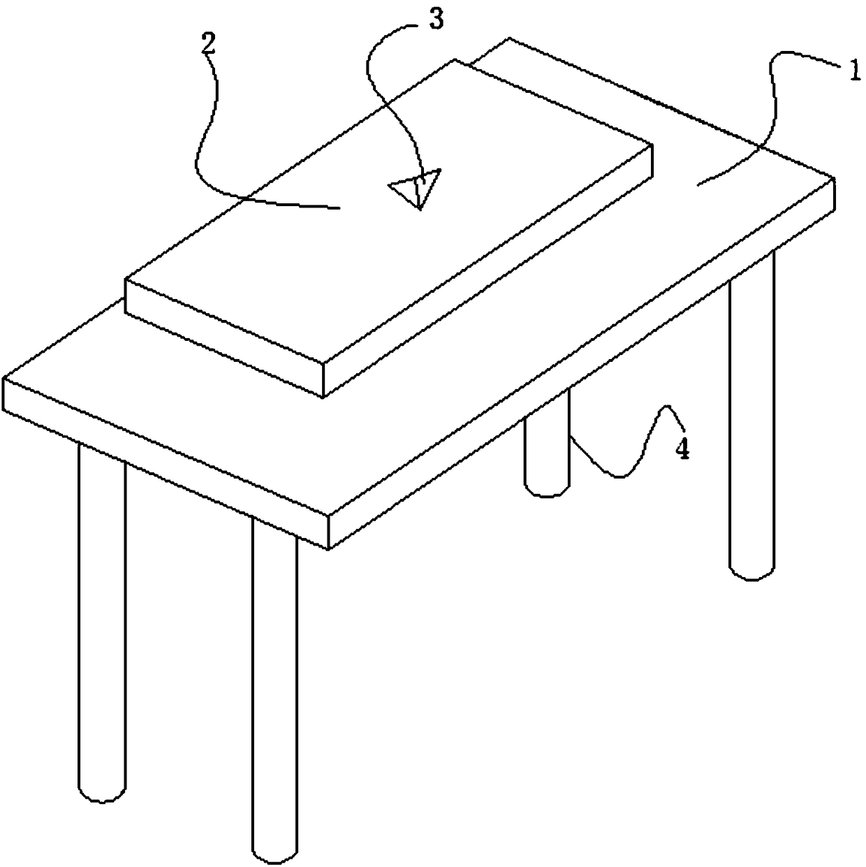
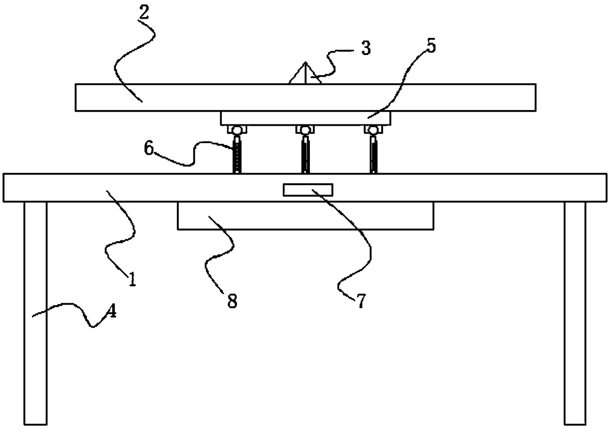
[0023] see Figure 1~4 , in an embodiment of the present invention, a solar power generation canopy based on Mitsubishi mirror photosensitive, including a roof 1 and a photovoltaic power generation panel 2, four corners of the lower end of the roof 1 are respectively provided with a leg 4, the roof 1 is provided with a photovoltaic power generation panel 2, and the photovoltaic power generation panel 2 is electrically connected to the battery 8 located on the lower end surface of the roof 1. Mechanism connections are fixed.
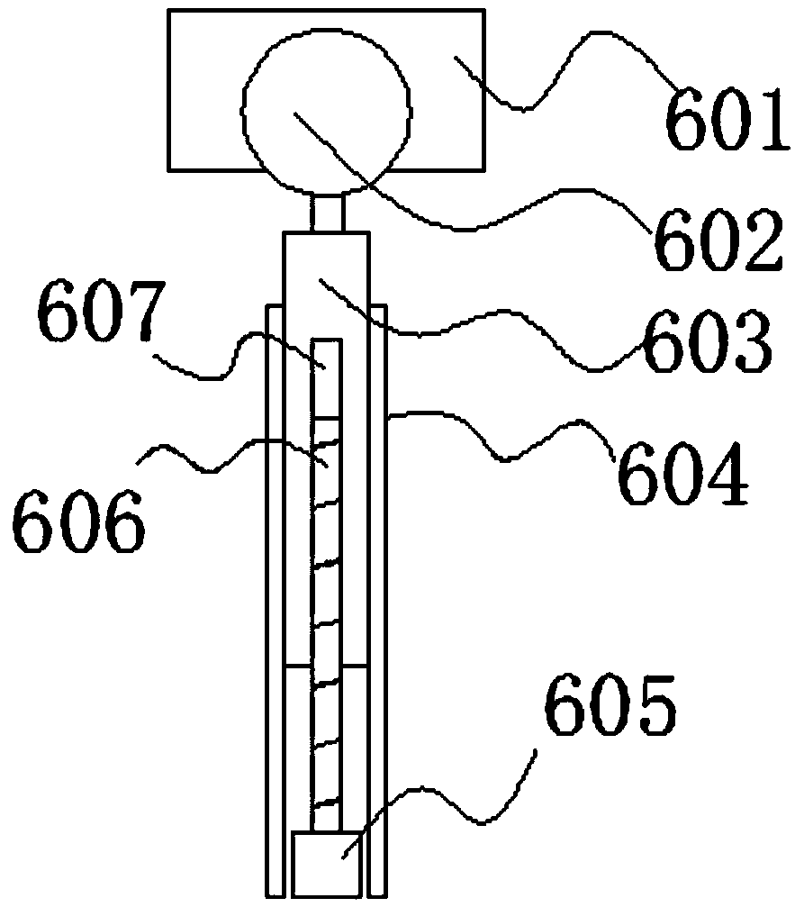
[0024] The angle adjustment mechanism includes a light-receiving detection block 3 located in the middle of the upper end surface of the photovoltaic power generation panel 2. The light-reception detection block 3 is used to detect whether the photovoltaic power generation panel 2 is perpendicular to the sunlight. The support block 5 is connected and fixed with the photovoltaic power generation panel 2 through bolts. The lower end surface of the support ...
Embodiment 2
[0029] The difference from Embodiment 5 is that: the roof 1 is also provided with a cleaning mechanism, the cleaning mechanism includes a horizontal plate 10 arranged horizontally above the roof 1, and the left and right ends of the horizontal plate 10 connect with the roof 1 through the support rods 9. The connection is fixed, and a transmission screw 12 is horizontally arranged under the horizontal plate 10. The right end of the transmission screw 12 is connected to the output end of the drive motor 11, and the left end of the transmission screw 12 is connected to the support rod 9 in rotation. The transmission screw 12 is pierced with a sliding block 13, the sliding block 13 is threadedly connected with the drive screw 12, and the upper end surface of the sliding block 13 is in sliding contact with the surface of the horizontal plate 10, the lower end surface of the sliding block 13 is equipped with a mounting plate 14, and the lower end surface of the mounting plate 14 is pr...
Embodiment 3
[0031] The difference from Embodiment 2 is that in order to reduce the frictional force, the upper end of the sliding block 3 is provided with a pulley against the horizontal plate 10, and the horizontal plate 10 is provided with a chute matched with the pulley, thereby switching the sliding friction into rolling friction.
PUM
 Abstract
Description
Claims
Application Information
 - R&D
- Intellectual Property
- Life Sciences
- Materials
- Tech Scout
- Unparalleled Data Quality
- Higher Quality Content
- 60% Fewer Hallucinations
Browse by: Latest US Patents, China's latest patents, Technical Efficacy Thesaurus, Application Domain, Technology Topic, Popular Technical Reports.
© 2025 PatSnap. All rights reserved.Legal|Privacy policy|Modern Slavery Act Transparency Statement|Sitemap|About US| Contact US: help@patsnap.com


