
Fore bracket for fully-mechanized mining face

A fully-mechanized mining face and advanced support technology, which is applied in the field of coal mining equipment, can solve the problems of easy damage to equipment, narrow roadways, and low coal seams, and achieve the goals of reducing the shape and weight, enhancing safety and reliability, and reducing labor intensity Effect

Pending Publication Date: 2019-02-12
GUIZHOU PANJIANG MINING MACHINERY
View PDF0 Cites 2 Cited by
  • Summary
  • Abstract
  • Description
  • Claims
  • Application Information

AI Technical Summary

Problems solved by technology

Some manufacturers have previously designed advanced hydraulic supports for roadways at both ends. However, this support is modified on the basis of ordinary hydraulic supports. Poor adaptability and other problems, especially in mines in southern my country, where the geological conditions are harsh, the coal seams are low, and the roadways are narrow, so they cannot be used at all
In the past, three rows of single capped point columns were added within 20m for advance support, and the row spacing between columns was 1200×1000mm. Manual erection and retraction of single columns were labor-intensive, and there was a danger of touching hands and feet when moving single columns , and it is easy to cause secondary loosening of the surrounding rock of the roof, especially when the roof is under obvious pressure and the surrounding rock is broken, the two sides of the roadway will bulge out and deform, and the roof will sink, reducing the section of the roadway and causing poor ventilation , A series of problems that the equipment is easy to damage directly restrict the normal coal mining of the working face, which is extremely unfavorable to safe production

Method used


Image

  • Fore bracket for fully-mechanized mining face
  • Fore bracket for fully-mechanized mining face

Examples


Embodiment 1

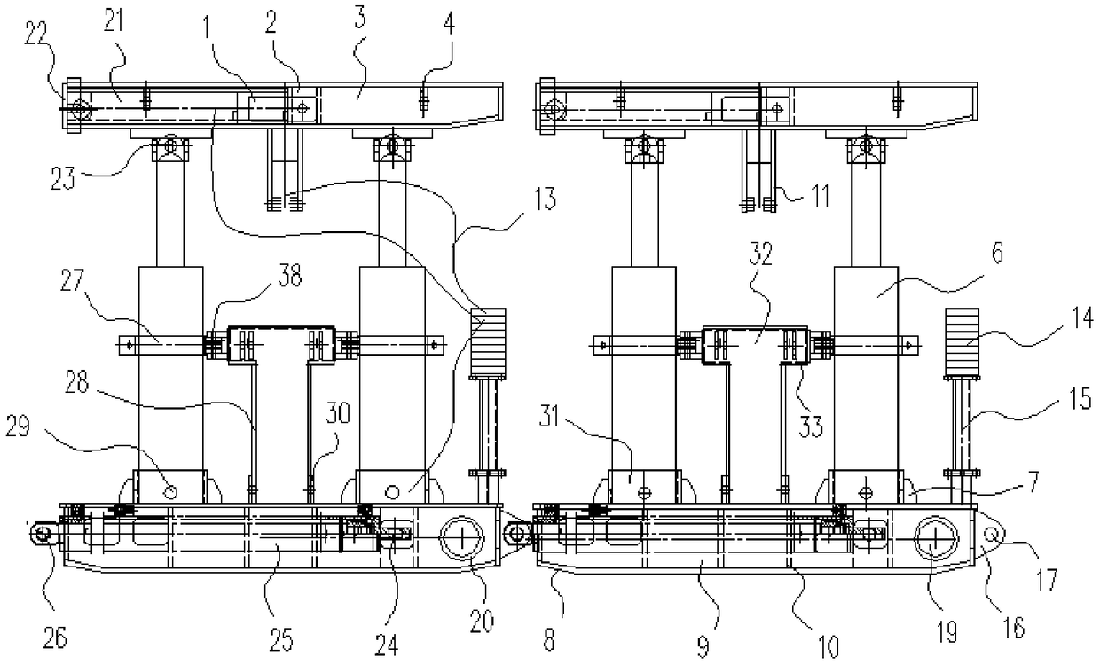
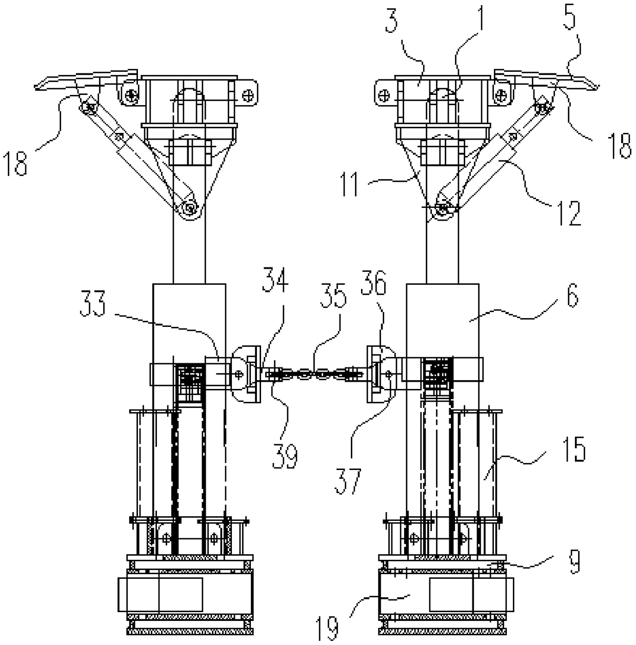
[0018] Embodiment 1: as attached Figure 1~2 Shown, a kind of advance support of fully mechanized mining face, it comprises base 9, oil cylinder one 6 and top frame 3, and described top frame 3 is positioned at the top of base 9 and is connected by two oil cylinders one 6 in the middle, on top frame 3 The upper end of the rear side is hinged with a side wall plate 5, and two symmetrical support plates 11 are fixedly connected in the middle below the top frame 3, and an oil cylinder 2 12 is hinged between the lower end of the support plate 11 and the bottom of the side wall plate 5, One end of the inside of the top frame 3 is provided with an oil cylinder three 1, an oil cylinder four 19 and an oil cylinder five 25 are arranged inside the base 9, and the side of the base 9 is fixedly connected with a valve seat rod 15, and the valve seat rod 15 is connected with several Reversing valve 14, described reversing valve 14 is respectively connected with oil cylinder one 6, oil cylin...


PUM


Abstract

The invention discloses a fore bracket for a fully-mechanized mining face. The fore bracket comprises bases, two first oil cylinders and top brackets. The top brackets are located above the bases, andare connected by the first oil cylinders. Lateral wall plates are hinged to the upper ends of the rear sides of the top brackets. Two supporting plates are symmetrically fixedly connected to the middles below the top brackets. Second oil cylinders are hinged between the lower ends of the supporting plates and the lower parts of the lateral wall plates. Third oil cylinders are arranged at one endsin the top brackets. Fourth oil cylinders are arranged at one ends in the bases. Valve seat posts are fixedly connected to the lateral sides of the bases. A plurality of reversing valves are connected to the valve seat posts. The reversing valves are respectively connected with the first, second, third, fourth and fifth oil cylinders by oil pipes. A lightweight design idea is adopted. The fore bracket has the characteristics of being small in size, low in weight, and high in supporting intensity, being convenient to convey underground and being excellent in adaptability. The fore bracket is especially suitable for production environment conditions of narrow roadways in low coal seams in south China, and obvious application effects are achieved.

Description

technical field [0001] The invention relates to an advance support, in particular to an advance support for a fully mechanized mining face, and belongs to the technical field of coal mining equipment. Background technique [0002] In the roadways at both ends of the coal mining face, the traditional support method is to manually use a single hydraulic prop to support the roof or a single unit with a hinged top beam to temporarily support the roof. This manual method has low support strength and small support area. , the labor intensity of personnel is high, the danger of falling columns is great, the support technology is backward, and the number of people is employed, which is not conducive to safe production; it cannot meet the requirements of today's high-yield and efficient mines. For this reason, it is imminent to study the advanced hydraulic support support equipment for both ends of the fully mechanized mining face. Some manufacturers have previously designed advance...

Claims


Application Information

Patent Timeline
Patent Type & Authority Applications(China)
IPC IPC(8): E21D23/00E21D23/04E21D23/16
CPCE21D23/0004E21D23/0418E21D23/16
Inventor 王正王金强孙伟罗书明任芸
Owner GUIZHOU PANJIANG MINING MACHINERY
Learn More