
Joint leak detection device

A leak detection and ventilation device technology, which is applied to measuring devices, detects the appearance of fluid at the leak point, and tests the machine/structural components, etc., can solve the problems of increased replacement costs, poor reliability, and low work efficiency, and achieve reduction Cost, effect of reliable leak detection

Active Publication Date: 2020-11-06
HEFEI HUALING CO LTD +2
View PDF6 Cites 0 Cited by
  • Summary
  • Abstract
  • Description
  • Claims
  • Application Information

AI Technical Summary

Problems solved by technology

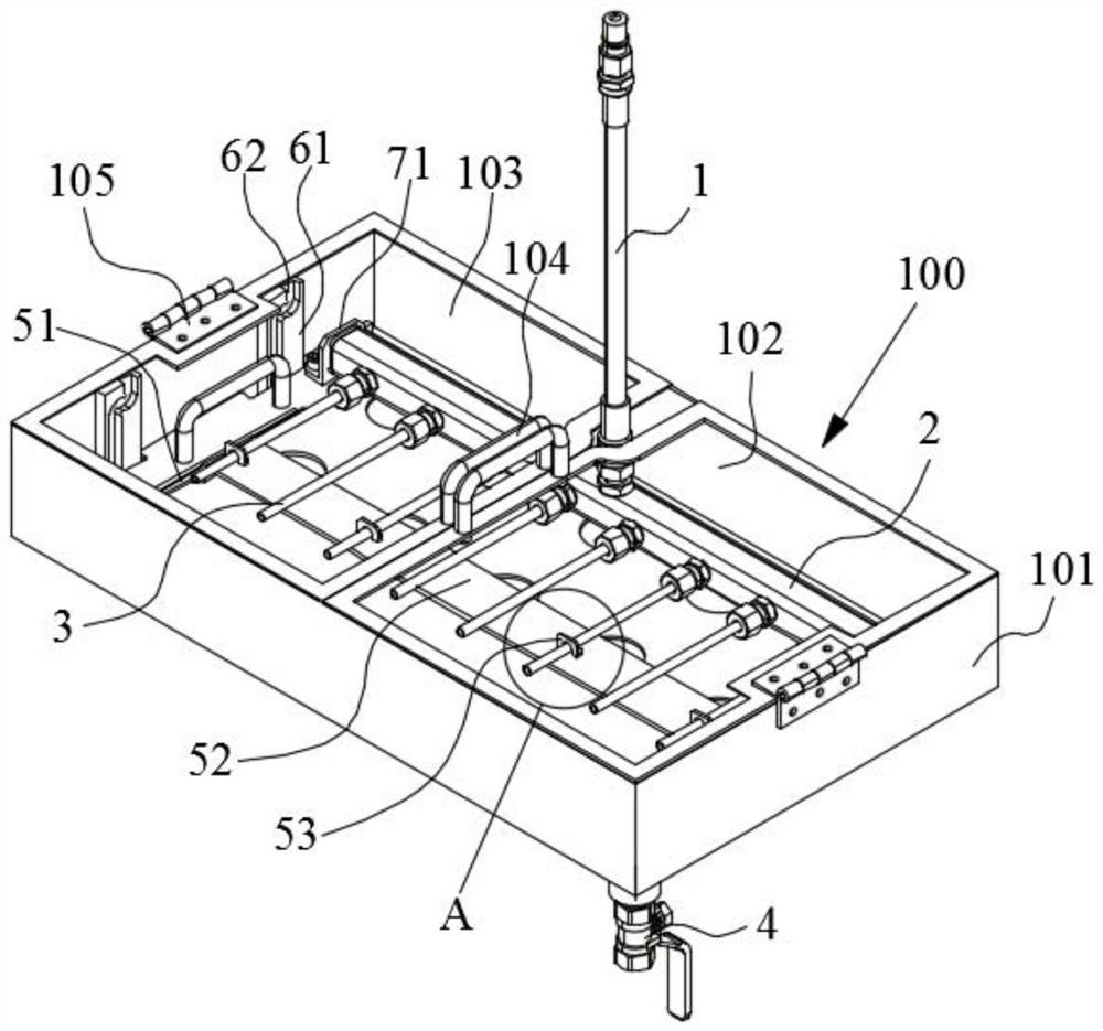
[0004] The main purpose of the present invention is to provide a joint leak detection device, which aims to solve the technical problems of low work efficiency, poor reliability and increased replacement cost in the prior art when joint leak detection

Method used


Image

  • Joint leak detection device
  • Joint leak detection device

Examples


Embodiment Construction

[0023] It should be understood that the specific embodiments described here are only used to explain the present invention, but not to limit the present invention.

[0024] The technical solutions in the embodiments of the present invention will be clearly and completely described below in conjunction with the accompanying drawings in the embodiments of the present invention. Obviously, the described embodiments are only a part of the embodiments of the present invention, rather than all the embodiments. Based on the embodiments of the present invention, all other embodiments obtained by those of ordinary skill in the art without creative work shall fall within the protection scope of the present invention.

[0025] It should be noted that all directional indicators (such as up, down, left, right, front, back...) in the embodiments of the present invention are only used to explain the relationship between components in a specific posture (as shown in the accompanying drawings) If t...


PUM


Abstract

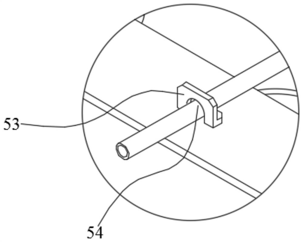
The present invention discloses a joint leak detector. The joint leak detector comprises a casing for placing leak detection liquid and a venting device mounted on the casing, wherein the venting device comprises a main pipe and a branch pipe part connected with the main pipe; the branch pipe part comprises a branch pipe; the pipe orifice, away from the main pipe, of the branch pipe is a connection port of a to-be-detected joint; the branch pipe portion is hinged in the casing to ensure that the branch pipe is capable of rotating between a working position and a raising position; at the working position, the connection port of the branch pipe is located in the casing; and at the raising position, the connection port of the branch pipe is located outside the casing. The joint leak detectoris capable of solving the technical problem of the joint leak detection in the prior art that the work efficiency is low, reliability is poor and the replacement cost is high.

Description

Technical field [0001] The invention relates to the technical field of industrial detection equipment, and in particular to a joint leak detection device. Background technique [0002] Quick joint is a kind of pipe joint that can be quickly dismantled and replaced without the use of tools. This joint has compact structure, high pressure resistance, interchangeability and lightness and flexibility. It is currently widely used in aerospace, metallurgy, mining, forging, coal Pipeline systems such as hydraulic and pneumatic transmission and lubricating fluid transmission of various mechanical equipment such as oil, petroleum and machine tools. [0003] However, the quick connector products in the prior art are prone to leakage problems caused by wear of the sealing ring, loose connection and other reasons during long-term use. For this kind of problem, the traditional solution is to check whether the sealing ring is worn or not, or directly replace it regularly. These methods are low ...

Claims


Application Information

Patent Timeline
Patent Type & Authority Patents(China)
IPC IPC(8): G01M3/08
CPCG01M3/085
Inventor 刘引朋田松徐高维
Owner HEFEI HUALING CO LTD
Learn More