Stainless steel flange turning blade

A stainless steel and blade technology, applied in the field of metal cutting, can solve the problem that the blade cannot take into account both roughing and finishing, and achieve good chip breaking effect, guaranteed strength, and the effect of expanding the scope

Pending Publication Date: 2019-02-15
OKE PRECISION CUTTING TOOLS CO LTD
View PDF0 Cites 5 Cited by
  • Summary
  • Abstract
  • Description
  • Claims
  • Application Information

AI Technical Summary

Problems solved by technology

[0005] The technical problem to be solved by the present invention is to provide a blade that can ensure sufficient strength of the blade during rough machining and also meet the requirements of the workpiece during finishing machining. Surface finish of turning inserts for stainless steel flanges

Method used


Image

  • Stainless steel flange turning blade
  • Stainless steel flange turning blade
  • Stainless steel flange turning blade

Examples


Embodiment 1

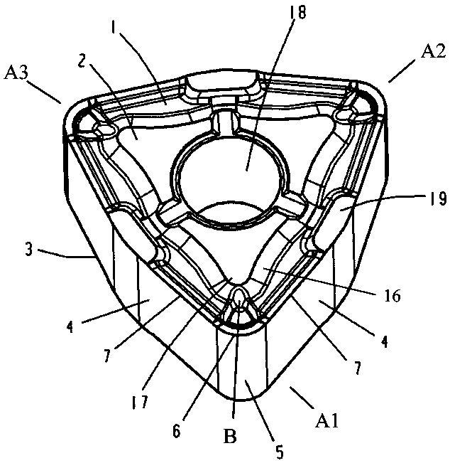
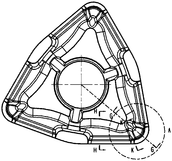
[0035] Such as figure 1 As shown, a turning blade for stainless steel flanges, the above-mentioned blade body 1 is provided with a positioning center hole 18 at its geometric center; the blade body 1 is a polygonal body. The geometric structure of a hexagon that is approximately equilateral and not equiangular; the above-mentioned blade body 1 includes an upper surface 2, a lower surface 3, a plurality of side surfaces 4, and an arc surface 2 between two adjacent side surfaces 4 ; The blade body 1 is provided with a positioning center hole 18 located at its geometric center;

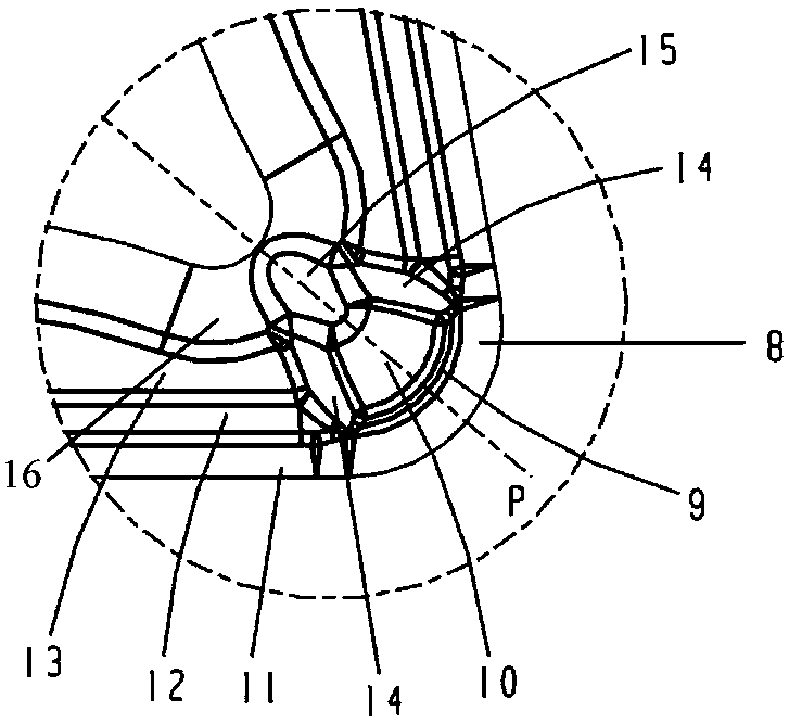
[0036] The upper surface 2 of the blade body 1 is evenly provided with a plurality of protrusions-17 along the periphery of the positioning center hole 18; on the outside of the two adjacent protrusions-17, and at the place where the two side surfaces 4 intersect to form an obtuse angle and the upper The central point of the junction of the surfaces 2 is provided with a protrusion 2 19 . In the present...


PUM


Abstract

The invention relates to the technical field of metal cutting machining, in particular to a stainless steel flange turning blade. The stainless steel flange turning blade comprises a blade body with apolygon body. The blade body is provided with a plurality of first protruding parts along the periphery of a positioning center hole, and second protruding parts are located on the outer sides of every two adjacent first protruding parts. Cutting units are arranged on the vertex corners of the blade body. Each cutting unit comprises a main cutting edge, an arc cutting edge and a scrap breaking unit. Each scrap breaking unit is composed of a first scrap breaking table, a first front blade face, a second front blade face, a scrap breaking groove bottom plane, a scrap containing groove and a half-moon-shaped protruding part. The edge width at the position of each arc cutting edge and the angle of a first front corner at the position of each arc cutting edge are larger than the edge width atthe position of the corresponding main cutting edge and the angle of a first front corner at the position of the corresponding main cutting edge. According to the turning blade, the strength of the cutting edges is combined while the sharpness of the cutting edges is guaranteed. Through the design of the double scrap cutting tables and the design of the half-moon-shaped protruding parts, the cutting blade has a good scrap breaking effect during stainless steel flange rough machining and finish machining.

Description

technical field [0001] The invention relates to the technical field of metal cutting, and more particularly relates to a turning insert for stainless steel flanges. Background technique [0002] As passenger and freight trains continue to increase in speed, the requirements for brake parts are also increasing. In the past, the material of flanges was usually QT450, which is an easy-to-process workpiece. Nowadays, most flanges are made of stainless steel. Stainless steel is a difficult-to-machine material. In machining, there are problems such as large work hardening tendency, low thermal conductivity, fast tool wear, serious bonding between chips and tools, and difficult chip breakage. Therefore, the processing of stainless steel flanges puts forward higher requirements for cutting tools. [0003] At present, stainless steel flange materials include 304, 304L, 316, 316L, 316Ti, etc., and the same blade is used for rough and fine machining, which requires our tools to have s...

Claims


Application Information

Patent Timeline
Patent Type & Authority Applications(China)
IPC IPC(8): B23B27/00B23B27/22
CPCB23B27/00B23B27/22B23B2200/049B23B2200/286B23B2200/32B23B2200/321
Inventor 周焱强李树强袁美和谭文清
Owner OKE PRECISION CUTTING TOOLS CO LTD
Why Eureka
Try Eureka