Dedicated clamp for processing upper die and processing method

A special fixture and mold processing technology, which is applied in metal processing equipment, metal processing machinery parts, clamping, etc., can solve the problems that ordinary milling machines are difficult to adapt to the processing of different upper mold cutting edge angles, and achieve convenient disassembly and increased contact The supporting area and the effect of high positioning accuracy

Pending Publication Date: 2019-02-15
ANHUI LIYUAN NUMERICAL CONTROL CUTTING TOOL & PATTERNS MFG
View PDF11 Cites 3 Cited by
  • Summary
  • Abstract
  • Description
  • Claims
  • Application Information

AI Technical Summary

Problems solved by technology

[0008] Aiming at the problem that the existing upper molds for bending machines have different bending angles, it is difficult to adapt to the processing of different upper mold cutting edge angles by using ordinary milling machines, the present invention provides a special fixture for upper mold processing, which can adjust the required milling process of the upper mold The angle of the cutting edge surface, so that the cutting edge surface of the upper mold to be processed is in a relatively horizontal state, and the cutting edge surface can be milled efficiently without changing the structure of the milling machine

Method used


Image

  • Dedicated clamp for processing upper die and processing method
  • Dedicated clamp for processing upper die and processing method
  • Dedicated clamp for processing upper die and processing method

Examples


Embodiment 1

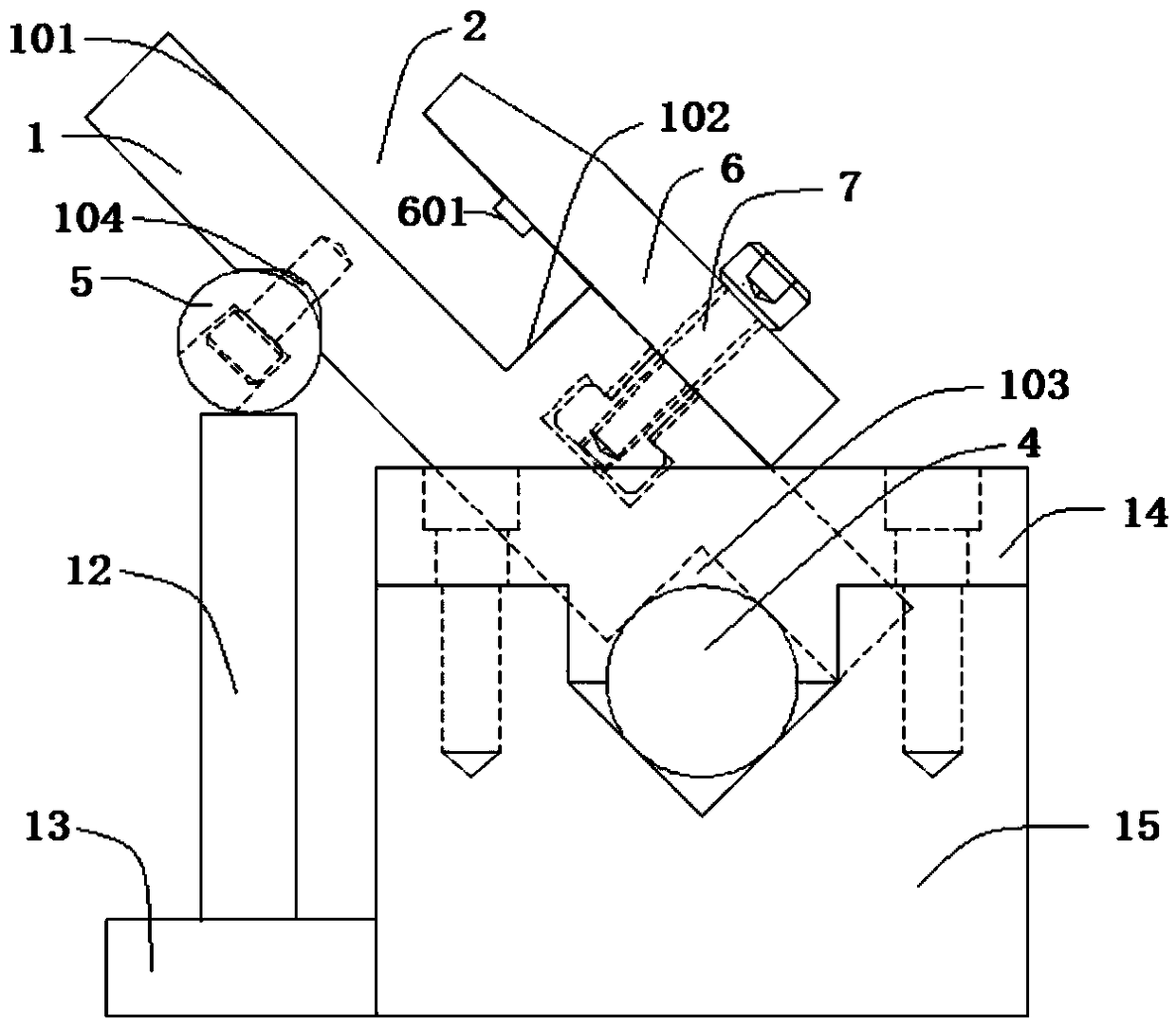
[0054] A special fixture for upper mold processing in this embodiment includes a mold base 1, a lower support member 4, an upper adjustment member 5 and an angle adjustment mechanism.

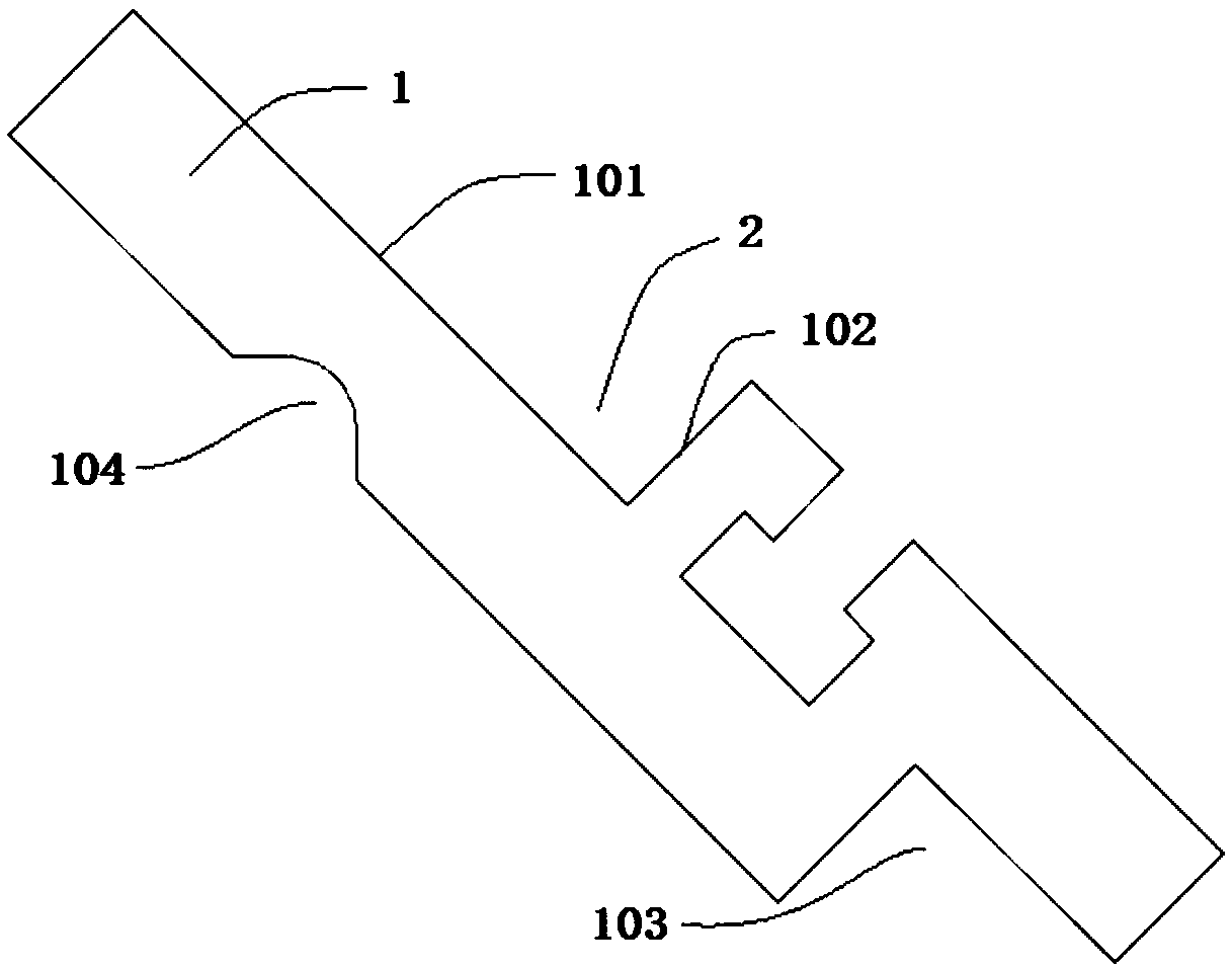
[0055] to combine image 3 and Figure 5 As shown, the mold base 1 includes a supporting surface 101, a positioning surface 102, a lower limiting groove 103 and an upper limiting groove 104; The space formed is used as the clamping position 2 of the clamping upper mold 3; the lower limit groove 103 is a right-angle groove, which is located at the lower end of the bottom surface of the mold base 1, and the lower limit groove 103 is matched with a cylindrical lower support 4; the upper limit Groove 104 is an arc groove, is located at the upper end position near the bottom surface of mold base 1, and the upper regulating part 5 of cylindrical shape is placed in the upper limit groove 104; Die base 1 is fixedly placed on the base 15.

[0056] The upper part of the lower support 4 contacts the two...

Embodiment 2

[0072]In order to solve the situation that the processing force in the processing process in embodiment 1 is too large and the support column 12 is not fixed stably, a special fixture for upper mold processing in this embodiment has a structure basically the same as that of embodiment 1, and the difference is that: Such as figure 1 As shown, the angle adjustment mechanism of the present embodiment includes a support column 12 and a support platform 13, and a support platform 13 is welded and fixed at the bottom of the support column 12, that is, the upper adjustment member 5 is supported and arranged on the upper end surface of the support column 12, and the support column 12 A support platform 13 is welded below, and the support surface of the support platform 13 is larger than the bottom surface of the support column 12, ensuring that the support column 12 can be placed firmly.

[0073] The existing upper mold 3 with the cutting edge surface 301 and the support surface 101 a...

Embodiment 3

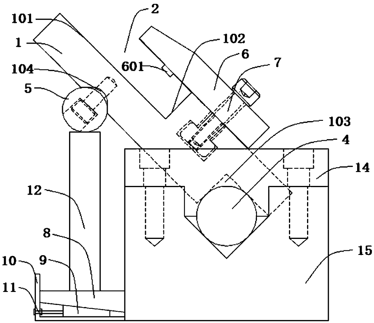
[0079] In order to solve the need to replace the length of the support column 12 to support and fix the upper adjustment member 5 in the first embodiment, which causes too much labor and effort in the production and processing process, and to achieve the accuracy of fine-tuning the height of the support column 12, a method of this embodiment The special fixture for upper mold processing is basically the same in structure as in Embodiment 1, except that: figure 2 As shown, the angle adjustment mechanism of this embodiment includes a pair of wedges fitted with inclined planes, an adjustment bolt 11 and a guide limiting member 10 .

[0080] In a pair of wedges, the upper wedge 8 supports the upper adjustment member 5, and the guide limiter 10 is used to limit the horizontal movement of the upper wedge 8; the adjustment bolt 11 is rotatably installed on the guide limiter 10, and its end is In a pair of wedges, the lower wedge 9 is rotatably connected, and the cross-sectional leng...


PUM


Abstract

The invention discloses a dedicated clamp for processing an upper die and a processing method, and belongs to the field of die steel processing devices. The dedicated clamp comprises a die holder, a lower supporting piece, an upper adjusting piece and an angle adjusting mechanism; the die holder is provided with a clamping position where the upper die is arranged; the lower supporting piece and the upper adjusting piece are movably connected with the two ends of the die holder; the angle adjusting mechanism is connected with the upper adjusting piece; the die holder can be driven to rotate with the lower supporting piece as a supporting point through the upper adjusting piece, so that the angle of an upper die cutting edge surface is adjusted, and the upper die cutting edge surface is arranged at the horizontal processing position; and the distance between the lower supporting piece and a standard supporting surface is determined by a digital model, that is, the rotating angle of the die holder is determined, and the distance is finely adjusted through the combination with a pair of wedge blocks of which the inclined surfaces are matched so as to mill the upper die cutting edge surface with small angle change. The structure of the milling machine can be not replaced, the upper die cutting edge surface of different angles can be milled, high positioning precision of the upper die cutting edge surface is ensured, and the supporting stability of the clamp is high.

Description

technical field [0001] The invention belongs to the field of die steel processing equipment, and more specifically relates to a special fixture and processing method for upper die processing. Background technique [0002] Grinding and milling is a common processing technology for steel, which is mainly used for grinding, polishing and grooving on the surface of steel. Generally speaking, the grinding and milling of the workpiece is directly processed on the milling table of the milling machine, but for some workpieces with irregular shapes or large volumes, it is not convenient to process directly on the milling machine. Especially for the upper mold used on the bending machine, to meet the bending needs of different products, the bending degree of the upper mold also changes accordingly, and the bending accuracy of the upper mold is very high, which makes the processing of the upper mold difficult. Various bending angles. [0003] For the processing of upper molds with di...

Claims


Application Information

Patent Timeline
Patent Type & Authority Applications(China)
IPC IPC(8): B23Q3/06B23Q3/04
CPCB23Q3/04B23Q3/062
Inventor 张波张一帆王克文
Owner ANHUI LIYUAN NUMERICAL CONTROL CUTTING TOOL & PATTERNS MFG
Why Eureka
Try Eureka