Prefabricated plate and shear wall connecting structure and construction method thereof

A technology of connecting structures and prefabricated shear force, which is applied in the direction of building structure and construction, can solve problems such as single form, end damage, and great influence on construction quality, and achieve simple structural design, broad application prospects, and good seismic performance Effect

Pending Publication Date: 2019-02-15
FUJIAN UNIV OF TECH
View PDF0 Cites 3 Cited by
  • Summary
  • Abstract
  • Description
  • Claims
  • Application Information

AI Technical Summary

Problems solved by technology

[0003] The prefabricated shear wall structure has many engineering applications at present. The current connection between the shear wall and the floor is mainly through cast-in-place. Most of the floors are laminated slabs. Into the shear wall, post-cast concrete to form a whole. This method has a large amount of concrete pouring, low prefabrication rate, and still has a lot of on-site wet work. The site also needs to bind the steel bars of the cast-in-place part, which cannot give full play to the advantages of the prefabricated type.
[0004] The connection between the floor slab and the shear wall is the key part of the stress. The end of the existing laminated slab is stressed. If it is strengthened at the end during construction, it can only be realized by configuring more steel bars. If no reinforcement is added to the original In the case of
[0005] After the shear wall and the floor are integrated, the connection between the lower shear wall and the upper shear wall i

Method used


Image

  • Prefabricated plate and shear wall connecting structure and construction method thereof
  • Prefabricated plate and shear wall connecting structure and construction method thereof
  • Prefabricated plate and shear wall connecting structure and construction method thereof

Examples


Example Embodiment

[0024] In order to make the above-mentioned features and advantages of the present invention more comprehensible, the following specific embodiments are described in detail with reference to the accompanying drawings.

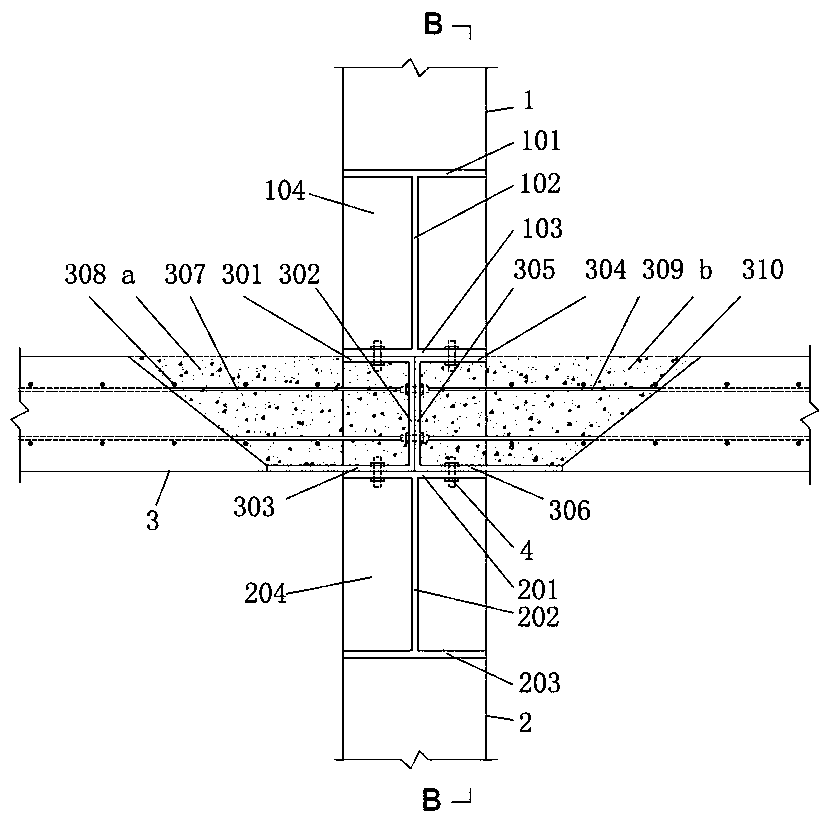
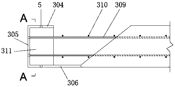
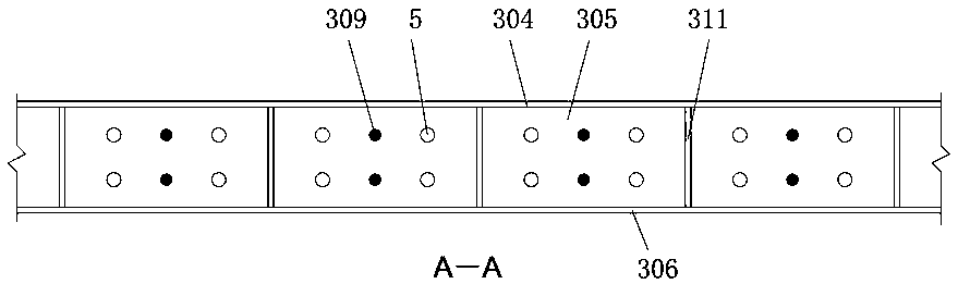
[0025] like Figure 1~4 As shown, a connection structure between a prefabricated slab 3 and a shear wall includes a first prefabricated shear wall 1, a second prefabricated shear wall 2 and a prefabricated slab 3, and the first prefabricated shear wall 1 is arranged on the prefabricated slab 3 above, the second prefabricated shear wall 2 is set under the prefabricated slab 3, the first prefabricated shear wall 1 contains the embedded steel of the first shear wall, and the second prefabricated shear wall 2 contains the first Two shear wall pre-embedded steel, the prefabricated plate 3 includes the first plate pre-embedded steel and the second plate pre-embedded steel, the first plate pre-embedded steel is connected with the second plate pre-embedded steel throug...


PUM


Abstract

The invention relates to a prefabricated plate and shear wall connecting structure, and further relates to a construction method of the prefabricated plate and shear wall connecting structure. The prefabricated plate and shear wall connecting structure comprises a first prefabricated shear wall, a second prefabricated shear wall and a prefabricated plate; the first prefabricated shear wall comprises first shear wall pre-buried profile steel, the second prefabricated shear wall comprises second shear wall pre-buried profile steel, and the prefabricated plate comprises first plate pre-buried profile steel and second plate pre-buried profile steel; and the first plate pre-buried profile steel and the second plate pre-buried profile steel are connected through bolts, the first shear wall pre-buried profile steel is connected with the first plate pre-buried profile steel and the second plate pre-buried profile steel through bolts, and the second shear wall pre-buried profile steel is connected with the first plate pre-buried profile steel and the second plate pre-buried profile steel through bolts. The structural design is simple and reasonable, connecting is reliable, the anti-seismicproperty is good, ductility is good, construction is convenient, high efficiency, convenience and rapidness are achieved, and thus the wide application prospects are achieved.

Description

technical field [0001] The invention relates to a connection structure between a prefabricated panel and a shear wall and a construction method. Background technique [0002] The use of prefabricated structures can save energy, water, and materials, greatly reduce construction waste, reduce noise pollution, reduce labor consumption and intensity, effectively improve the construction environment, and improve project quality, so it is favored by researchers and engineering designers. , is a structure worthy of promotion. In prefabricated structures, seam connection technology is the key technology, which is the key to ensure structural integrity and seismic performance. [0003] The prefabricated shear wall structure has many engineering applications at present. The current connection between the shear wall and the floor is mainly through cast-in-place. Most of the floors are laminated slabs. Into the shear wall, post-cast concrete to form a whole. This method has a large am...

Claims


Application Information

Patent Timeline
IPC IPC(8): E04B1/38E04B1/41
CPCE04B1/38E04B1/41E04B2001/4192
Inventor 郑永乾杨少坤郑莲琼张雪丽
Owner FUJIAN UNIV OF TECH
Why Eureka
Try Eureka