
A Dissolution Controllable Dissolvable Bridge Plug

A controllable and bridge plug technology, applied in wellbore/well components, sealing/isolation, earthwork drilling and production, etc., can solve the problems of chemical pollution, cost increase, construction can not be completed on time, etc., and achieve good time matching , cost saving, simple and practical effect

Active Publication Date: 2021-08-03
大庆市宏博晟达石油机械设备有限公司
View PDF6 Cites 0 Cited by
  • Summary
  • Abstract
  • Description
  • Claims
  • Application Information

AI Technical Summary

Problems solved by technology

Under normal circumstances, this is no problem, but if there are special circumstances, such as the cooperation unit is not in place on time, the construction will not be completed on time. If the bridge plug has been dissolved and failed at this time, then it must wait for it to completely dissolve Afterwards, the bridge plug will be reinstalled, which will undoubtedly bring additional material costs and time costs
In addition, there is another situation, because the existing dissolvable bridge plug starts to dissolve as soon as it enters the well. In order to allow sufficient time for construction, the speed of bridge plug dissolution must be controlled, but if the construction progresses quickly, all construction will be completed However, it is necessary to wait for the dissolution of the bridge plug to be completed. At this time, in order to speed up the dissolution of the bridge plug, sometimes a cosolvent is injected into the well, which not only increases the cost, but also brings potential chemical pollution.

Method used


Image

  • A Dissolution Controllable Dissolvable Bridge Plug
  • A Dissolution Controllable Dissolvable Bridge Plug
  • A Dissolution Controllable Dissolvable Bridge Plug

Examples


Embodiment Construction

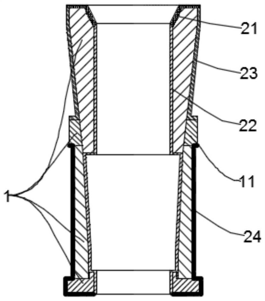
[0031] The technical solutions in the embodiments of the present invention will be clearly and completely described below in conjunction with the drawings in the present invention. Apparently, the described embodiments are only some of the embodiments of the present invention, not all of them. Based on the embodiments of the present invention, all other embodiments obtained by persons of ordinary skill in the art without making creative efforts belong to the protection scope of the present invention.

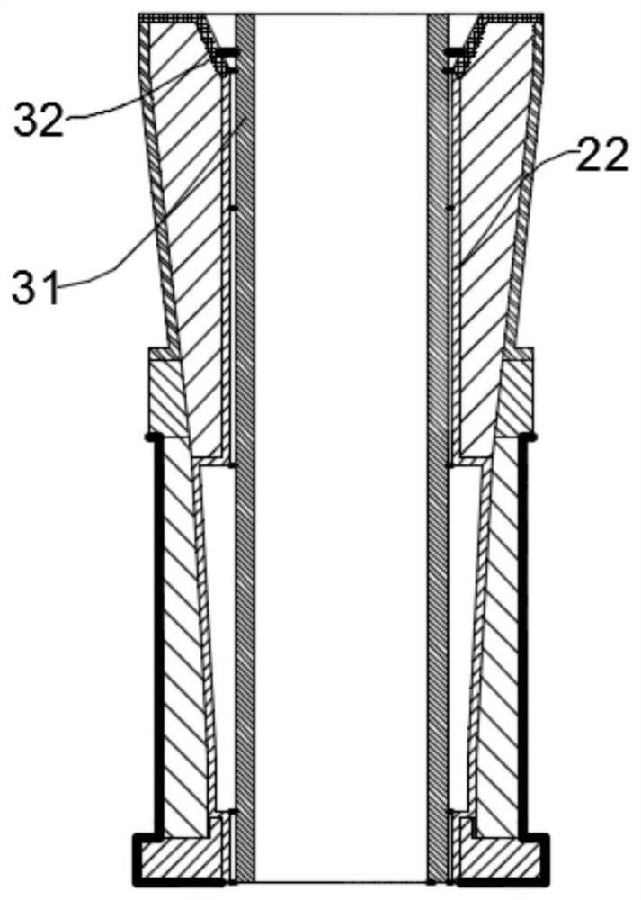
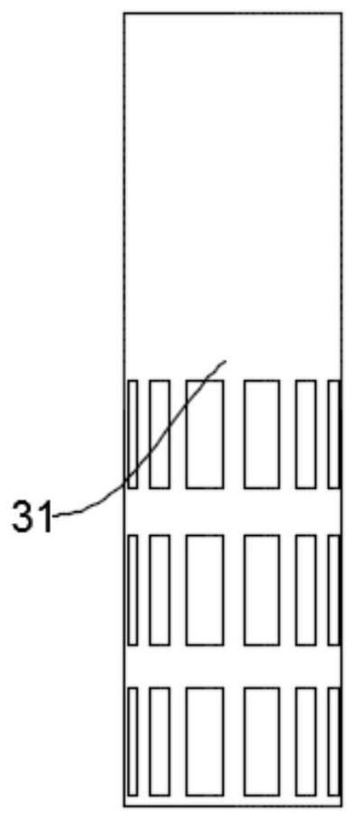
[0032] Such as figure 1 As shown, a dissolving controllable soluble bridge plug according to the embodiment of the present invention includes a fast-dissolving bridge plug body 1 and a slow-dissolving layer attached to the inner and outer surfaces of the fast-dissolving bridge plug body 1. After the slow-dissolving layer is destroyed, the internal fast-dissolving bridge The plug body 1 is exposed and starts to dissolve.

[0033] In the dissolution controllable soluble bridge pl...


PUM


Abstract

The invention relates to the technical field of petroleum exploitation, in particular to a controllable dissolution bridge plug, comprising an instant bridge plug body and a slow-dissolving layer attached to the inner and outer surfaces of the instant bridge plug body, and the instant bridge inside after the slow-dissolution layer is destroyed The body of the plug is exposed and begins to dissolve. The inner and outer surfaces of the fast-dissolving bridge plug body of the present invention are attached with a slow-dissolving layer, and the protection of the slow-dissolving layer prevents the bridge plug from rapidly dissolving after it enters the well, and it cannot be maintained until the fracturing is completed and then becomes invalid; in addition, the slow-dissolving layer is equipped with a mechanical Destroy the structure and destroy the slow-dissolving layer, thereby exposing the body of the fast-dissolving bridge plug for dissolution. The structure is simple, and the pressing of the fracturing ball is used as the trigger signal to realize the synchronization of fracturing construction and dissolution, thus avoiding unfinished fracturing construction However, the bridge plug was dissolved and failed ahead of time, saving the cost of implanting a new bridge plug.

Description

technical field [0001] The invention relates to the technical field of petroleum exploitation, in particular to a dissolution controllable soluble bridge plug. Background technique [0002] Bridge plug refers to a tool used in the process of oil and gas exploitation and transportation to cut off gas and liquid transportation channels. In the process of developing low-porosity and low-permeability oil and gas fields represented by shale gas, bridge plugs are widely used in staged and layered fracturing processes to block harmful gas and liquid transportation and pressure transmission channels, restricting Pressure fluid enters the destination layer. After the fracturing operation is completed, it is generally necessary to remove the bridge plugs installed during the fracturing process. The earliest method of removing bridge plugs was to drill holes in the bridge plugs through coiled tubing. This method not only has high costs and high construction safety risks, but also mak...

Claims


Application Information

Patent Timeline
Patent Type & Authority Patents(China)
IPC IPC(8): E21B33/134
CPCE21B33/134
Inventor 李代甫
Owner 大庆市宏博晟达石油机械设备有限公司
Learn More