Miniaturized pneumatic-hydraulic linkage actuator for large-diameter valve and low air source
A pneumatic actuator, large-diameter technology, applied in the direction of valve operation/release device, valve details, valve device, etc., can solve the problems of limited output force, frequent fluctuation of air source pressure, and synchronous transmission of air and oil, etc. Achieve the effect of reducing the size and volume, reducing space occupation, and expanding the application conditions
- Summary
- Abstract
- Description
- Claims
- Application Information
AI Technical Summary
Problems solved by technology
Method used
Image
Examples
Embodiment 1
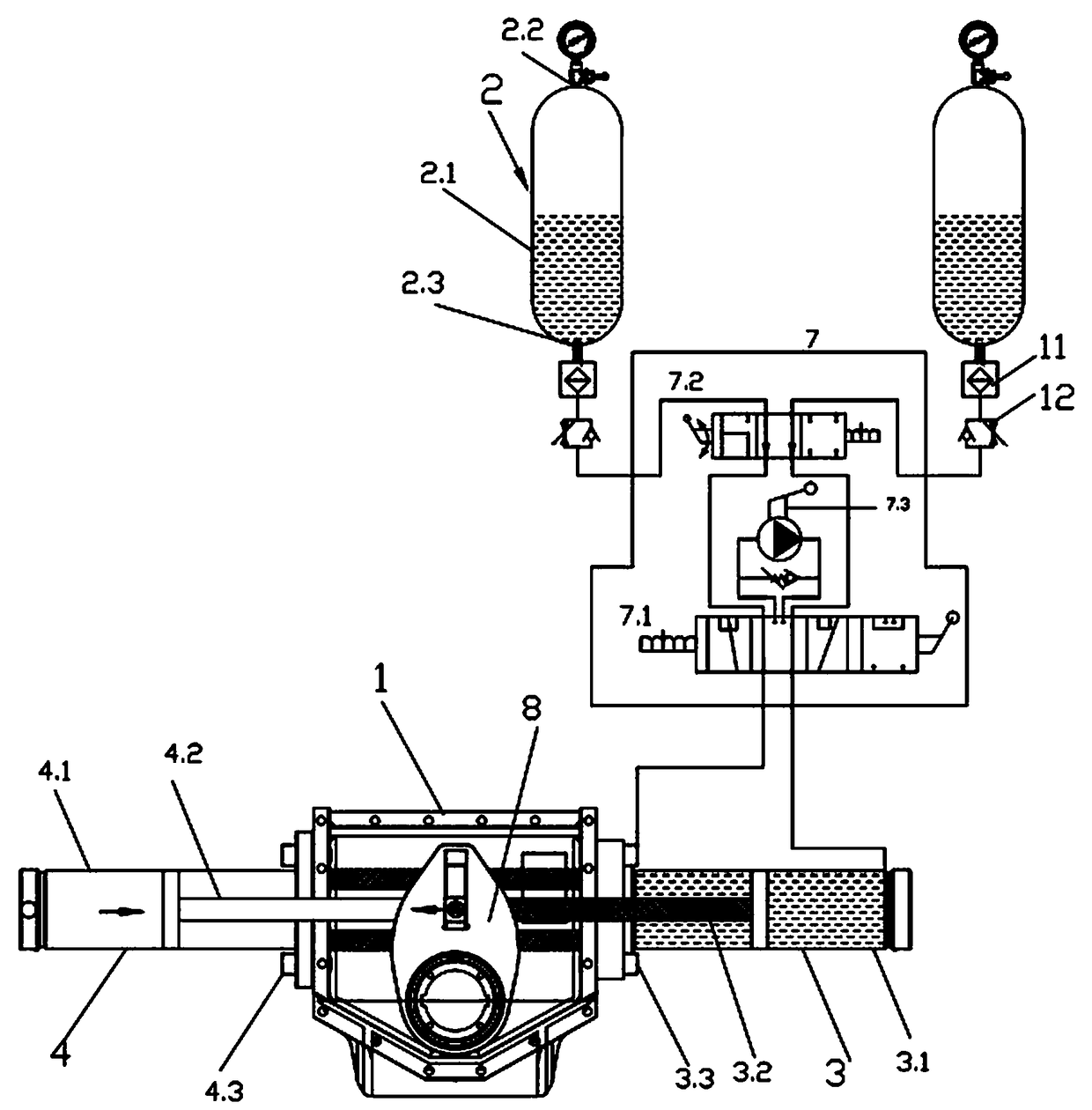
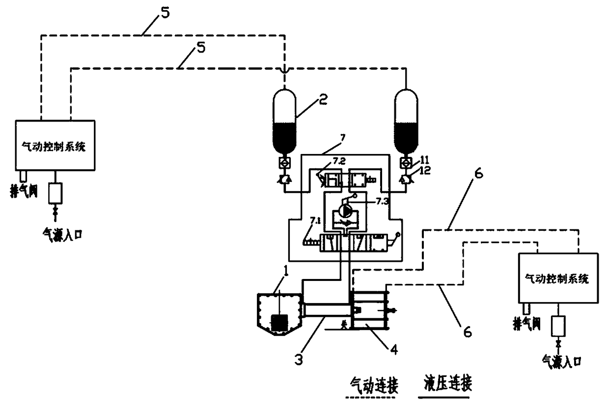
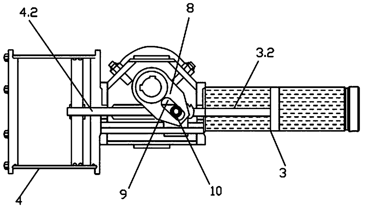
[0042] Such as figure 1 As shown, the pneumatic actuator is installed on one side of the shift fork transmission box 1 ( figure 1 is the left side), the hydraulic actuator is installed on the other side of the shift fork transmission box 1 ( figure 1 is the right side), the output mechanism of the pneumatic actuator is connected to the output mechanism of the hydraulic actuator, the fork drive slider 10 is provided on the fork transmission block, and the fork 8 of the fork transmission box 1 A bar-shaped chute 9 matched with the shift fork driving slider 10 is provided on the top.
[0043] The hydraulic actuator is a hydraulic cylinder 3, and the output mechanism of the hydraulic cylinder 3 is a first piston rod 3.2. The hydraulic cylinder 3 includes a first cylinder body 3.1 and a first cylinder block 3.3. The first cylinder body 3.1 The first cylinder base 3.3 is installed on the box body of the shift fork transmission box 1, and the first piston rod 3.2 passes through the...
Embodiment 2
[0057] Such as image 3 As shown, the difference between Embodiment 2 and Embodiment 1 is that an isolation bladder 2.4 is provided in the gas-liquid tank 2, and the opening of the isolation bladder 2.4 is sealed and installed on the air inlet and outlet 2.2, and the isolation bladder 2.4 seals the tank Body 2.1 The inner cavity is separated into a gas cavity and a liquid cavity, the inside is a gas cavity, and the outside is a liquid cavity.
[0058] Preferably, the air inlet and outlet 2.2 and the liquid inlet and outlet 2.3 are provided with connecting joints, and the isolation bladder 2.4 is connected to the connecting joints through a sealing assembly.
[0059] It works as follows:
[0060] Working condition 1: The pneumatic control system controls the air intake of the right air-liquid tank 2. When the right air-liquid tank 2 increases the air pressure, the isolation bladder 2.4 in the right isolation tank expands, and the hydraulic oil in the right isolation tank is sq...
Embodiment 3
[0065] Such as Figure 5 As shown, the difference between Embodiment 2 and Embodiment 1 is that the first pneumatic control system and the second pneumatic control system are independent pneumatic control systems. Principle is the same as embodiment 1.
PUM
 Abstract
Description
Claims
Application Information
 - R&D
- Intellectual Property
- Life Sciences
- Materials
- Tech Scout
- Unparalleled Data Quality
- Higher Quality Content
- 60% Fewer Hallucinations
Browse by: Latest US Patents, China's latest patents, Technical Efficacy Thesaurus, Application Domain, Technology Topic, Popular Technical Reports.
© 2025 PatSnap. All rights reserved.Legal|Privacy policy|Modern Slavery Act Transparency Statement|Sitemap|About US| Contact US: help@patsnap.com


