Cyclone separator
A cyclone separator and separator technology, applied in the direction of combustion types, lighting and heating equipment, incinerators, etc., can solve the problems of substandard emissions, poor temperature controllability, low energy utilization, etc., to reduce emissions and reduce residence time , Improve the effect of pyrolysis efficiency
- Summary
- Abstract
- Description
- Claims
- Application Information
AI Technical Summary
Problems solved by technology
Method used
Image

Examples
Embodiment 1
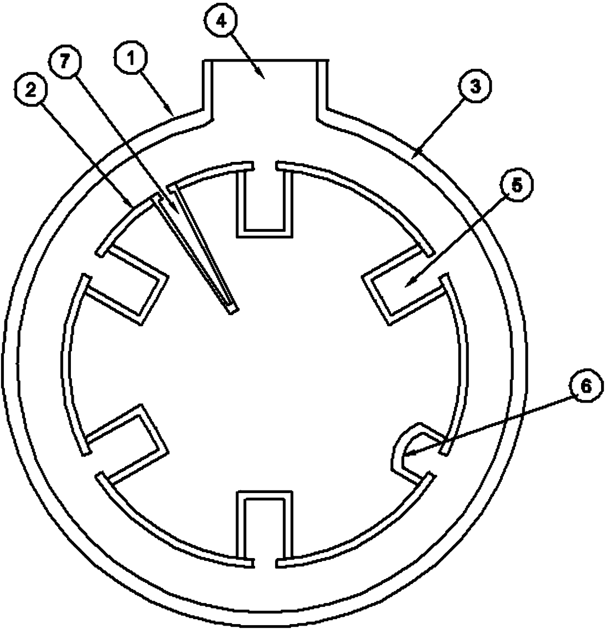
[0055] Such as figure 1 , 7 As shown in -8, the present invention provides a cyclone separator, including a tank body, a head 26, a cyclone separator inlet 25, a pyrolysis synthesis gas outlet 29, a solid particle outlet 34, and a first sealing flange plate 30 , the second sealing flange plate 31, the third sealing flange plate 32, the separator 27; the tank body and the sealing head 26 are sealed, and the pyrolysis synthesis gas outlet 29 is arranged on the sealing head 26 upper end; the solid particle outlet 34 is arranged at the lower end of the tank body; the first flange sealing plate 30, the second flange sealing plate 30, and the second flange sealing plate 30 are sequentially fixedly arranged between the tank body and the head 26 from top to bottom. A flange sealing plate 31, a third flange sealing plate 32; the cyclone separator inlet 25 is arranged on the side of the tank body between the first flange sealing plate 30 and the second flange sealing plate 31; The sep...
Embodiment 2
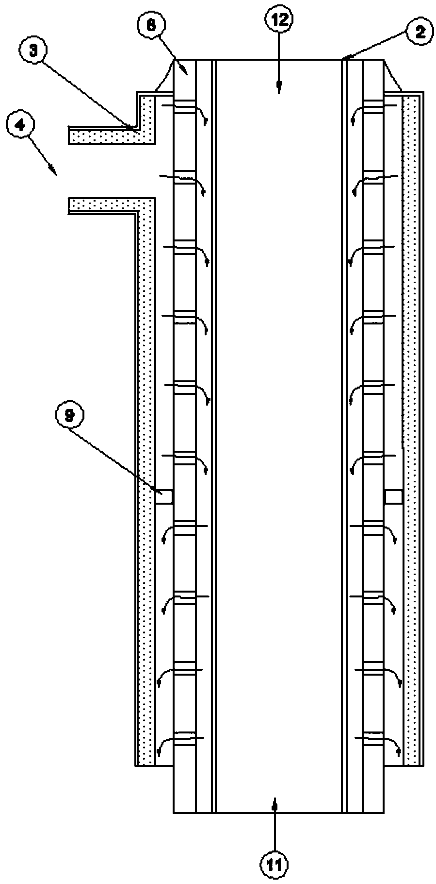
[0075] Such as figure 2 , 7 As shown in -8, the present invention provides a cyclone separator, including a tank body, a head 26, a cyclone separator inlet 25, a pyrolysis synthesis gas outlet 29, a solid particle outlet 34, and a first sealing flange plate 30 , the second sealing flange plate 31, the third sealing flange plate 32, the separator 27; the tank body and the sealing head 26 are sealed, and the pyrolysis synthesis gas outlet 29 is arranged on the sealing head 26 upper end; the solid particle outlet 34 is arranged at the lower end of the tank body; the first flange sealing plate 30, the second flange sealing plate 30, and the second flange sealing plate 30 are sequentially fixedly arranged between the tank body and the head 26 from top to bottom. A flange sealing plate 31, a third flange sealing plate 32; the cyclone separator inlet 25 is arranged on the side of the tank body between the first flange sealing plate 30 and the second flange sealing plate 31; The se...
Embodiment 3
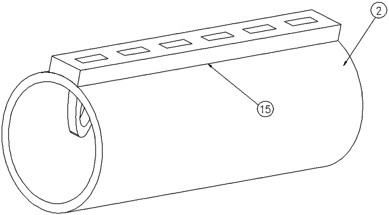
[0097] Such as Figures 3a-3c , 4. Shown in 7-8, the present invention provides a kind of cyclone separator, comprises tank body, end cap 26, cyclone separator inlet 25, pyrolysis synthesis gas outlet 29, solid particle outlet 34, also includes the first seal Flange plate 30, second sealing flange plate 31, third sealing flange plate 32, separator 27; said tank body and said head 26 are sealed and connected, and said pyrolysis synthesis gas outlet 29 is arranged at The upper end of the sealing head 26; the solid particle outlet 34 is arranged at the lower end of the tank body; the first flange sealing plate 30 is fixedly arranged sequentially from top to bottom between the tank body and the sealing head 26 , the second flange sealing plate 31, the third flange sealing plate 32; the cyclone separator inlet 25 is arranged on the tank body between the first flange sealing plate 30 and the second flange sealing plate 31 The side of the separator 27 runs through between the first ...
PUM
 Abstract
Description
Claims
Application Information
 - R&D
- Intellectual Property
- Life Sciences
- Materials
- Tech Scout
- Unparalleled Data Quality
- Higher Quality Content
- 60% Fewer Hallucinations
Browse by: Latest US Patents, China's latest patents, Technical Efficacy Thesaurus, Application Domain, Technology Topic, Popular Technical Reports.
© 2025 PatSnap. All rights reserved.Legal|Privacy policy|Modern Slavery Act Transparency Statement|Sitemap|About US| Contact US: help@patsnap.com