Method for measuring position of linear motor mover based on machine vision

A linear motor and mover position technology, applied in the direction of measuring devices, instruments, optical devices, etc., can solve the problems of noise sensitivity, large calculation errors, errors, etc.

Inactive Publication Date: 2019-02-15
深圳市深信创联智能科技有限责任公司
View PDF2 Cites 0 Cited by
  • Summary
  • Abstract
  • Description
  • Claims
  • Application Information

AI Technical Summary

Problems solved by technology

The essence of visual measurement methods is image matching. The commonly used matching algorithms are mainly divided into two categories: (1) Spatial measurement methods: such as the pixel-recursive algorithm (PRA), which can easily meet the real-time requirements, but is sensitive to noise, and in When the offset is large, the calculation error is large; (2) Frequency domain measurement methods: such as methods based on Fourier‐Mellin and phase correlation

Method used


Image

  • Method for measuring position of linear motor mover based on machine vision
  • Method for measuring position of linear motor mover based on machine vision
  • Method for measuring position of linear motor mover based on machine vision

Examples


Embodiment approach

[0031] As an implementation manner, the calculation step includes:

[0032] Preprocessing sub-step: use the Hanning (flap-top) window function to collect the image f 1 and f 2 Perform window function preprocessing to suppress spectrum leakage during Fourier transform and improve measurement accuracy and anti-interference performance. Among them, the expression of the Hanning window function is:

[0033]

[0034] Γ(m,n)=k×0.5(1-cos(2π(m / M)))×0.5(1-cos(2π(n / N)));

[0035] Among them, M and N are the size of the image, and k is the structure factor. The embodiment of the present invention finds an optimal window function by selecting different structure factors, which can better suppress spectrum confusion and is more conducive to subsequent calculations; when k is 1, the flap-top window function is the Hanning window function, so flap The -top window function has a wider range of applications.

[0036] As an implementation manner, the phase correlation algorithm includes...


PUM


Abstract

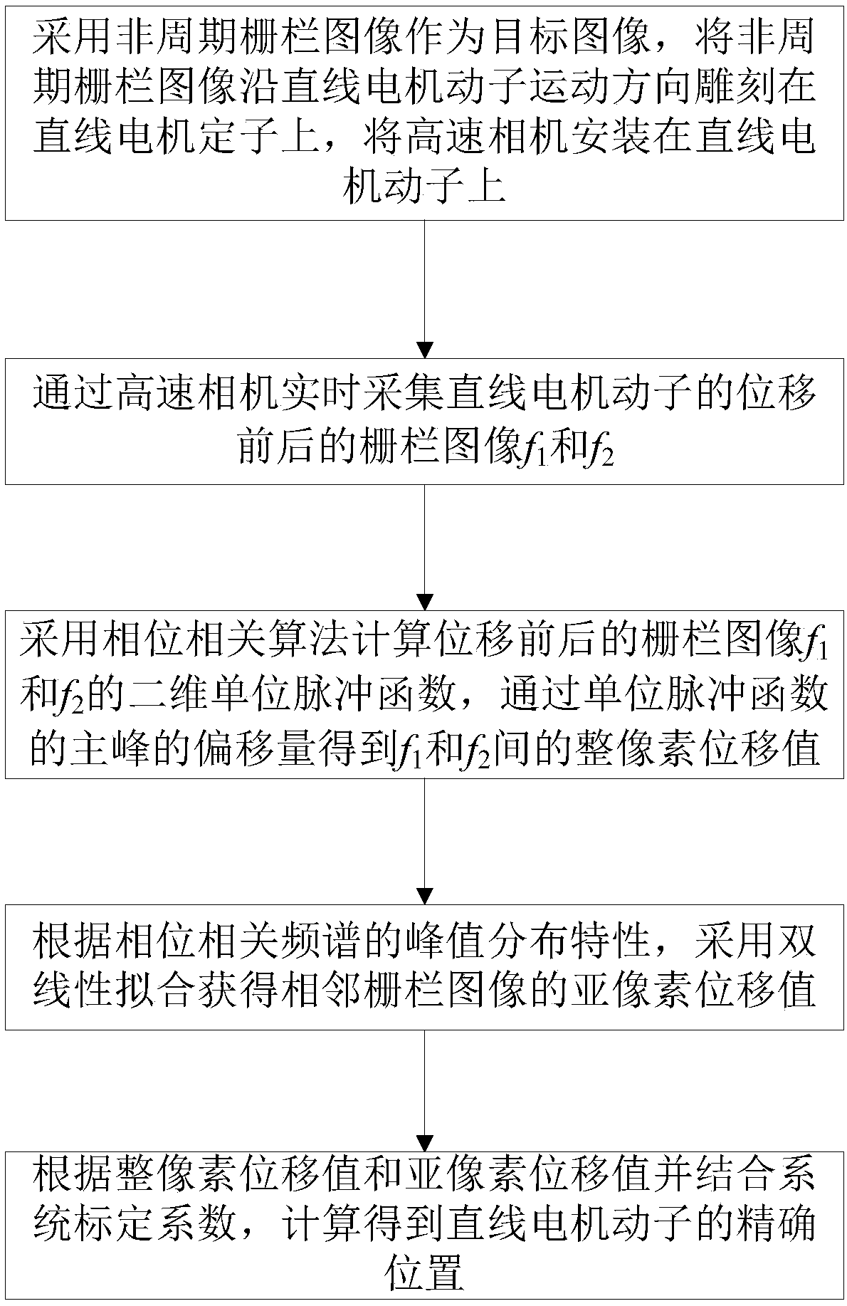
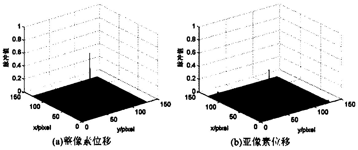
The invention discloses a method for measuring the position of the linear motor mover based on the machine vision, comprising the following steps: the preparation step, engraving a non-periodic fenceimage on the linear motor stator as a target image along the moving direction of the linear motor mover, and mounting a high speed camera on the linear motor mover; the acquisition step, acquiring thefence image of the linear motor mover by the high speed camera in real time; the calculation step, calculating a phase correlation function of the adjacent fence images using a phase correlation algorithm; the fitting step: obtaining a sub-pixel displacement value of the adjacent fence images by using a bilinear fitting according to a peak distribution characteristic of a phase correlation spectrum; the position acquisition step: calculating and obtaining the exact position of the linear motor mover in combination with a system calibration coefficient. According to the method for measuring position of linear motor mover based on machine vision, the horizontal pixel displacement value delta x between adjacent fence images is obtained by fitting the correlation peak and the surrounding peak. The pixel displacement value and the actual displacement value of the mover are calibrated to realize the precise displacement of the linear motor mover position.

Description

technical field [0001] The invention relates to the technical field of linear motor mover measurement, in particular to a machine vision-based method for measuring the position of a linear motor mover. Background technique [0002] The linear servo system has the characteristics of high precision, high acceleration, and large stroke, which make it more and more widely used in ultra-precision manufacturing. The detection accuracy of the mover position of the linear motor directly affects the control accuracy of the motor, and then determines the manufacturing accuracy of the product. Therefore, researching a high-precision linear motor mover position measurement method has important guiding significance for precision machining. [0003] The traditional linear motor mover position measurement mainly uses some sensors, such as magnetic grating, grating, laser interferometer, etc. There are many examples of position measurement and the technology is mature, but each has its own...

Claims


Application Information

Patent Timeline
IPC IPC(8): G01B11/00
CPCG01B11/00
Inventor 温鲜慧王爱玲
Owner 深圳市深信创联智能科技有限责任公司
Why Eureka
Try Eureka