A torque measuring device

A technology of torque measurement and torque, which is applied in the direction of measuring device, torque measurement, power measurement, etc., can solve the problems of complicated mechanical alignment, time-consuming, difficult installation, etc., and achieve simple and convenient installation and maintenance, and strong environmental adaptability , not easy to damage the effect

Active Publication Date: 2020-12-11
INST OF ELECTRICAL ENG CHINESE ACAD OF SCI
View PDF9 Cites 0 Cited by
  • Summary
  • Abstract
  • Description
  • Claims
  • Application Information

AI Technical Summary

Problems solved by technology

[0002] At present, most of the torque measuring devices measure the torque by measuring the strain of the strain gauge. Therefore, the measuring equipment is installed between the driving end and the driven end, which is difficult in many occasions with small spaces. Installation; on the other hand, good mechanical alignment is required, otherwise, it is easy to cause damage to the equipment under test or measuring equipment during high-speed rotation, and the mechanical alignment is cumbersome and time-consuming
At the same time, the strain gauge used for torque measurement is easily damaged by external force or harsh environment, and it is difficult to repair
Especially in high-speed testing, the dynamic balance characteristics of the coupling and the quality of the mechanical alignment have a great influence on the vibration and noise of the system, and at the same time reduce the accuracy of the torque measurement results

Method used


Image

  • A torque measuring device
  • A torque measuring device
  • A torque measuring device

Examples


Embodiment 1

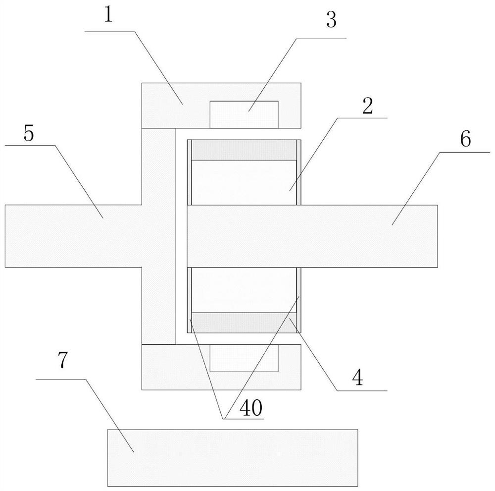
[0054] Such as figure 1 Shown, a kind of torque measuring device, described measuring device comprises:

[0055] Measuring module 7, electromagnetic coupling, driving end 5, driven end 6;

[0056] The electromagnetic coupling includes a squirrel-cage rotor and a permanent magnet rotor, the squirrel-cage rotor and the permanent magnet rotor are arranged coaxially, and a gap is provided between the squirrel-cage rotor and the permanent magnet rotor;

[0057] One of the squirrel-cage rotor or the permanent magnet rotor is connected to the driving end 5, and the other is connected to the driven end 6; the rotation of the driving end 5 drives the rotation of the driven end 6 ;

[0058] The measuring module 7 is used to obtain the rotational speed of the squirrel-cage rotor and the rotational speed of the permanent magnet rotor, and calculate the driving end 5 and the The torque transmitted between the driven ends 6.

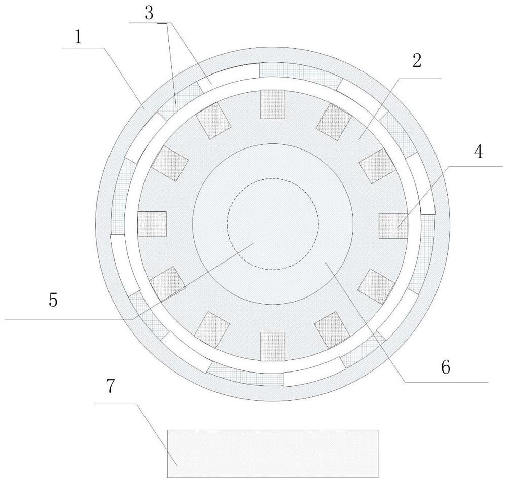
[0059] Such as figure 1 and figure 2 As shown, both the s...

Embodiment 2

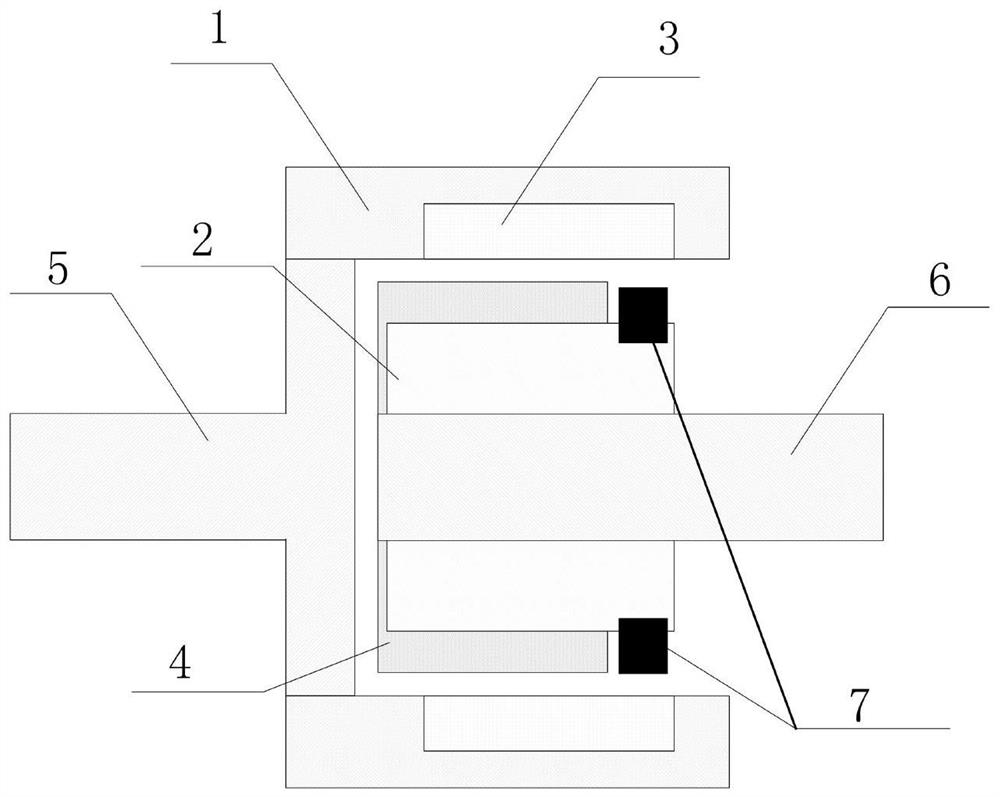
[0084] A torque measuring device, the measuring device comprising:

[0085] Measuring module 7, electromagnetic coupling, driving end 5, driven end 6;

[0086] The electromagnetic coupling includes a squirrel-cage rotor and a permanent magnet rotor, the squirrel-cage rotor and the permanent magnet rotor are arranged coaxially, and a gap is provided between the squirrel-cage rotor and the permanent magnet rotor;

[0087] One of the squirrel-cage rotor or the permanent magnet rotor is connected to the driving end 5, and the other is connected to the driven end 6; the rotation of the driving end 5 drives the rotation of the driven end 6 ;

[0088] The measurement module 7 is connected with the squirrel-cage rotor and the permanent magnet rotor, and the measurement module 7 is used to acquire the rotational speed of the squirrel-cage rotor and the rotational speed of the permanent magnet rotor, and according to the The rotation speed of the cage rotor and the rotation speed of t...

Embodiment 3

[0110] A torque measuring device, the measuring device comprising:

[0111] Measuring module 7, electromagnetic coupling, driving end 5, driven end 6;

[0112] The electromagnetic coupling includes a squirrel-cage rotor and a permanent magnet rotor, the squirrel-cage rotor and the permanent magnet rotor are arranged coaxially, and a gap is provided between the squirrel-cage rotor and the permanent magnet rotor;

[0113] One of the squirrel-cage rotor or the permanent magnet rotor is connected to the driving end, and the other is connected to the driven end; the rotation of the driving end drives the rotation of the driven end;

[0114] The measurement module 7 is connected with the squirrel-cage rotor and the permanent magnet rotor, and the measurement module is used to acquire the rotation speed of the squirrel-cage rotor and the rotation speed of the permanent-magnet rotor, and according to the Calculate the torque transmitted between the driving end 5 and the driven end 6 ...


PUM


Abstract

The invention discloses a measuring device for torque. The measuring device comprises a measuring module, an electromagnetic coupling, an active end, and a driven end. The electromagnetic coupling comprises a squirrel cage rotor and a permanent magnet rotor. The squirrel cage rotor is disposed coaxially with the permanent magnet rotor, and a gap is disposed between them. One of the squirrel cage rotor or the permanent magnet rotor is connected to the active end, and the other is connected to the driven end. The driving end rotates to drive the driven end to rotate. The measuring module is configured to obtain the rotational speeds of the squirrel cage rotor and the permanent magnet rotor, and calculate the torque transmitted between the active end and the driven end according to the rotational speeds of the squirrel cage rotor and the permanent magnet rotor. The electromagnetic coupling in the measuring device for torque can realize the coupling function without precise alignment, andthe installation and maintenance are simple and convenient.

Description

technical field [0001] The invention relates to the field of torque measurement, in particular to a torque measurement device. Background technique [0002] At present, most of the torque measuring devices measure the torque by measuring the strain of the strain gauge. Therefore, the measuring equipment is installed between the driving end and the driven end, which is difficult in many occasions with small spaces. Installation; on the other hand, a good mechanical alignment is required, otherwise, it is easy to cause damage to the equipment under test or the measuring equipment when rotating at high speed, and the mechanical alignment is cumbersome and time-consuming. At the same time, the strain gauge used for torque measurement is easily damaged by external force or harsh environment, and it is difficult to repair. Especially in high-speed testing, the dynamic balance characteristics of the coupling and the quality of the mechanical alignment have a great influence on the...

Claims


Application Information

Patent Timeline
Patent Type & Authority Patents(China)
IPC IPC(8): G01L3/10
CPCG01L3/104
Inventor 赵峰郭柯
Owner INST OF ELECTRICAL ENG CHINESE ACAD OF SCI
Why Eureka
Try Eureka